Rockwell Automation Publication PFLEX-IN015A-EN-P - March 2005 5
PowerFlex 700S and 700H Fan Inverter Upgrade Kit (Frame 9)
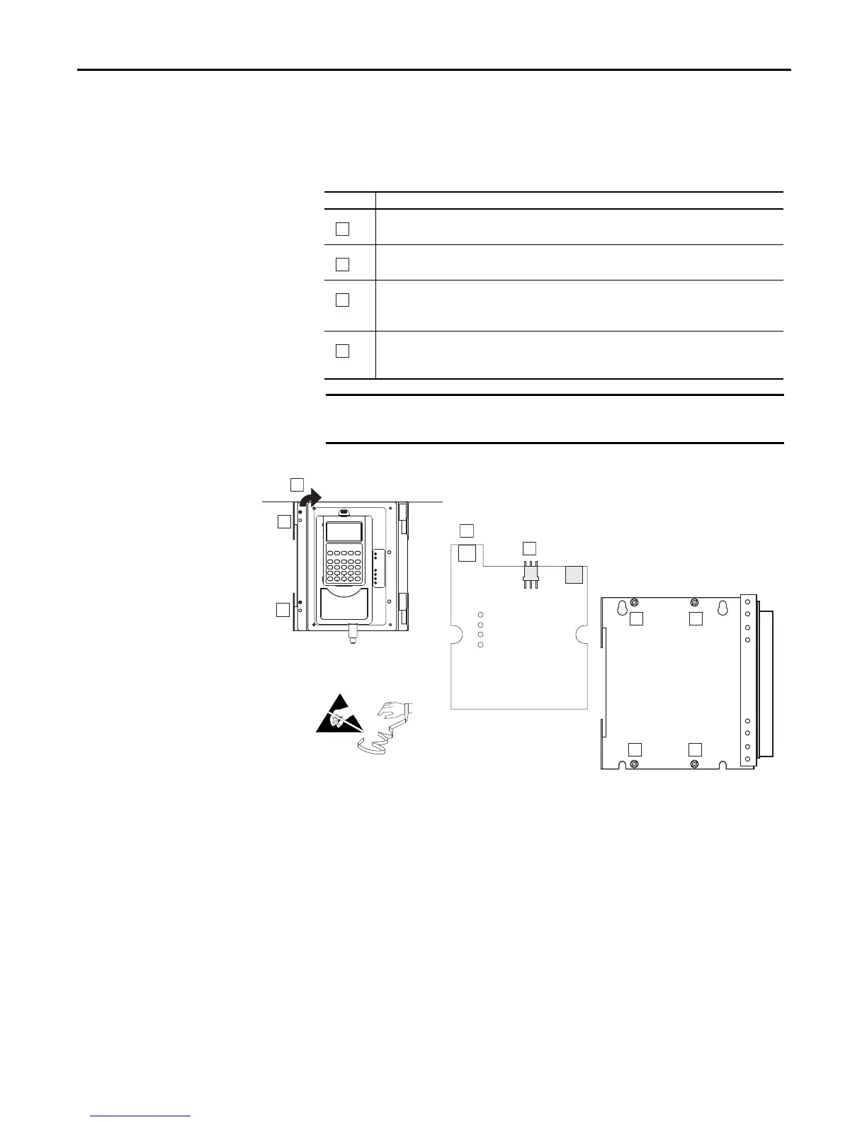
Step 3: Removing the
Components from the
Control Frame
DPI / HIM Assembly
You must remove the DPI / HIM Assembly from the Control Frame, in order to
gain access to the fasteners that secure the Control Frame to the drive.
Phillips is a registered trademark of Phillips Screw Company
Task Description
Remove the two M3x6 Phillips
®
screws, which secure the door on the front of the DPI / HIM Assembly.
Proper tightening torque for reassembly is 0.9 N•m (8 lb•in).
Open the door.
Unplug the DPI cable from the X2 connector.
Disconnect cables from communication adapter if present.
On 700S drives only, unplug the cable from the X4 connector.
Remove the four M3x6 Phillips screws, which secure the DPI / HIM Assembly to the Control Frame, and
remove the Assembly.
Proper tightening torque for reassembly is 0.9 N•m (8 lb•in).
B
C
C
D
D
D
D
Before removing connections and wires, mark the connections and wires to
avoid incorrect wiring during assembly.

 Loading...


