Rockwell Automation Publication PFLEX-IN015A-EN-P - March 2005 9
PowerFlex 700S and 700H Fan Inverter Upgrade Kit (Frame 9)
700H I/O Boards and Control Assembly (on 700H drives only)
On 700H drives, you must also remove the Control Assembly and I/O
boards.
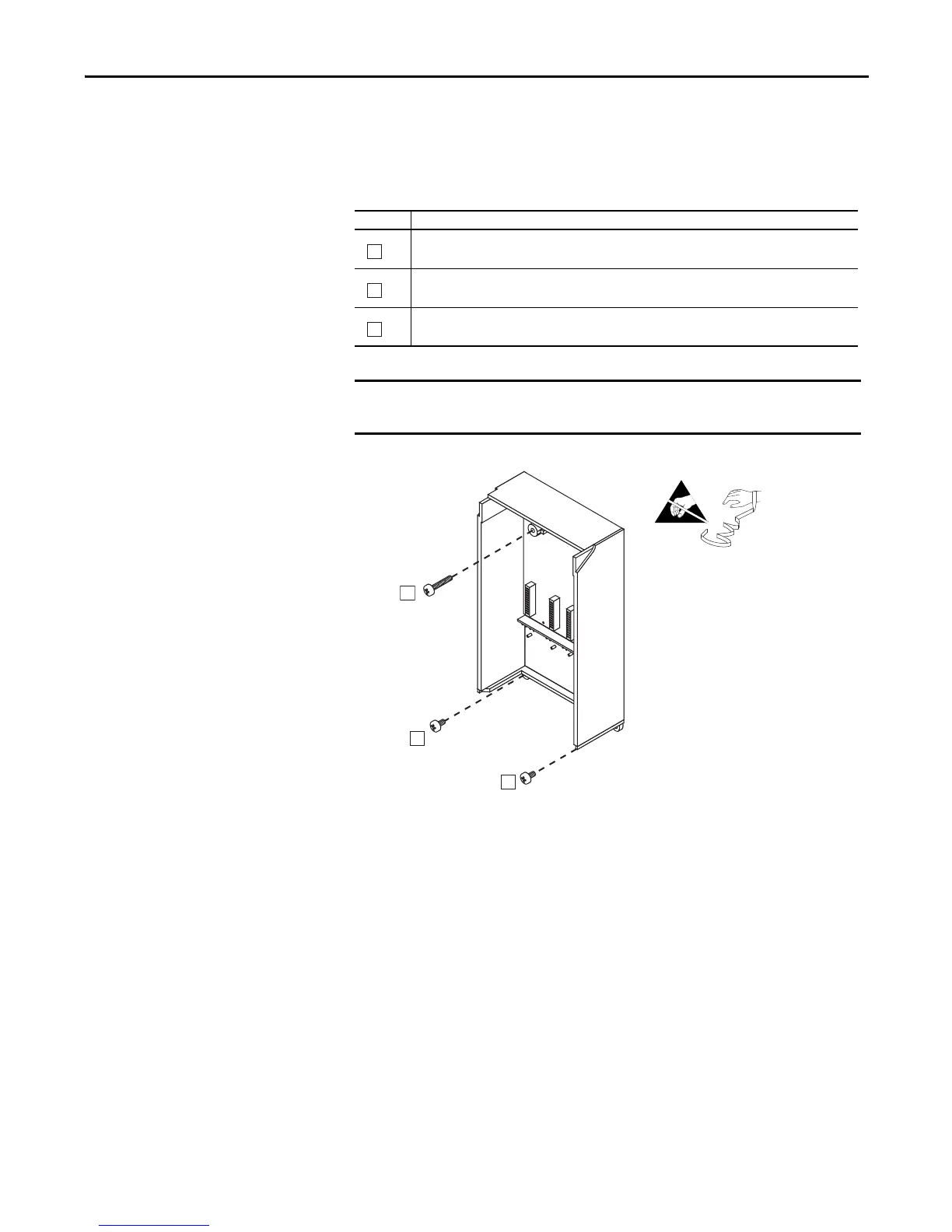
Task Description
Open the enclosure that contains the Control and I/O Boards and carefully unplug the DPI cable and any
I/O cables.
Remove the three M4 Pozidrive screws, which secure the Control Assembly to the drive.
Proper tightening torque for reassembly is 0.9 N•m (8 lb•in).
Remove the Control Assembly.
Before removing connections and wires, mark the connections and wires to
avoid incorrect wiring during assembly.
Do not remove enclosure cover or I/O
boards. Enclosure is illustrated without
the cover and boards for clarity.
B

 Loading...


