EasyManuals Logo

Allen-Bradley PowerFlex 700H Installation Instructions

Allen-Bradley PowerFlex 700H
22 pages
To Next Page IconTo Next Page
To Previous Page IconTo Previous Page
Page #10 background imageLoading...
Page #10 background image
10 Rockwell Automation Publication PFLEX-IN015A-EN-P - March 2005
PowerFlex 700S and 700H Fan Inverter Upgrade Kit (Frame 9)
Step 4: Removing the Control
Frame and Conduit
Task Description
If removing a Control Frame from a DC input drive with precharge interlock, disconnect the wiring from
terminal strip X50.
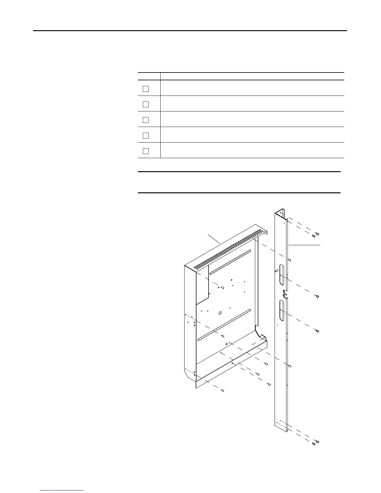
Remove the eight M4x8 Pozidrive screws, which secure the Control Frame to the drive.
Proper tightening torque for reassembly is 3 N•m (27 lb•in).
Remove the six M4x8 Pozidrive screws, which secure the Conduit to the drive.
Proper tightening torque for reassembly is 3 N•m (27 lb•in).
Remove the Conduit from the drive.
Remove the Control Frame from the drive while carefully routing the cables and wires through the access
hole of the Control Frame.
IMPORTANT
Before removing connections and wires, mark the connections and wires to
avoid incorrect wiring during assembly.
A
B
C
D
E
Control Frame
Conduit

Other manuals for Allen-Bradley PowerFlex 700H

Questions and Answers:

Question and Answer IconNeed help?

Do you have a question about the Allen-Bradley PowerFlex 700H and is the answer not in the manual?

Allen-Bradley PowerFlex 700H Specifications

General IconGeneral
BrandAllen-Bradley
ModelPowerFlex 700H
CategoryController
LanguageEnglish

Related product manuals