10 Rockwell Automation Publication 750-IN105D-EN-P - June 2018
PowerFlex 750-Series Service Cart and DC Precharge Module Lift
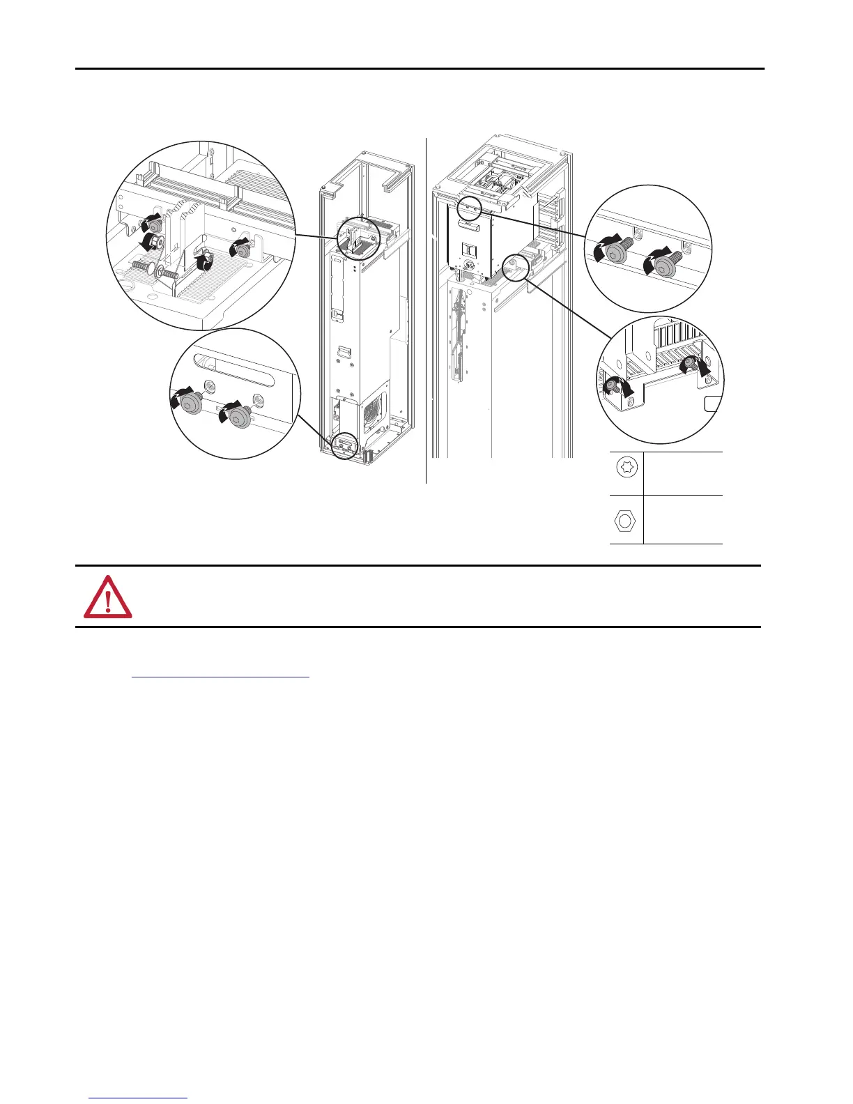
5. Remove the top anchor bolts.
Refer to image 2 for configurations that contain a DC prechrage module.
6. After the service cart is in position, remove the bottom anchor bolts.
See
Extract the Power Module on page 11 for more information.
Refer to image 2 for configurations that contain a DC precharge module.
ATTENTION: Avoid equipment damage or personal injury. If a natural disaster is anticipated or if a natural disaster is occurring, keep the bottom anchor bolts
attached until the service cart is prepared for the power module. Failure to do so could result in death, dismemberment, or damage to the product as the power
module could roll out of the cabinet.
2x
M10 x 20 mm
T45
42.4 N•m (375 lb•in)
M10
15 mm
38 N•m (336 lb•in)
Image 1
Image 2

 Loading...


