Rockwell Automation Publication 750-IN105D-EN-P - June 2018 11
PowerFlex 750-Series Service Cart and DC Precharge Module Lift
Extract the Power Module
Complete these procedures before you remove the power module.
•
Setup the Service Cart on page 4
•
Prepare the Equipment for Service on page 8
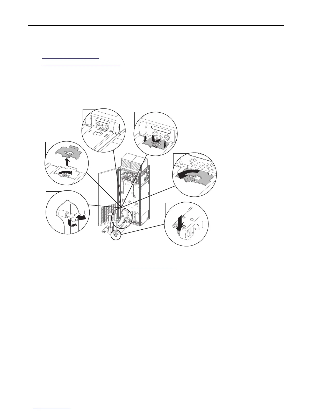
Follow these steps to remove the power module.
1. Prepare the LCL filter module or power module for removal. Verify wire harnesses, fiber-optic cables, and power and ground connections
are disconnected.
2. Set the two anchor pins on the vertical supports of the service cart to the unlocked position.
3. Remove the tie-in plate from the bridge span.
4. Align the service cart with the prepared module.
5. To connect the bridge span to the cabinet floor, insert the tie-in plate.
6. Engage the lock on the tie-in plate by turning the lock counter-clockwise.
7. Set the rear caster brakes on the service cart to the ON position.
TIP Adjust the height of the carriage assembly and the reach of the bridge span as needed. Adjustment allows the service cart to be level with cabinet floor
and align with the module wheel tracks. See
Adjust the Service Cart on page 7 for more information.
5
4
3
2
6
2x
7
2x

 Loading...


