12 Rockwell Automation Publication 750-IN105D-EN-P - June 2018
PowerFlex 750-Series Service Cart and DC Precharge Module Lift
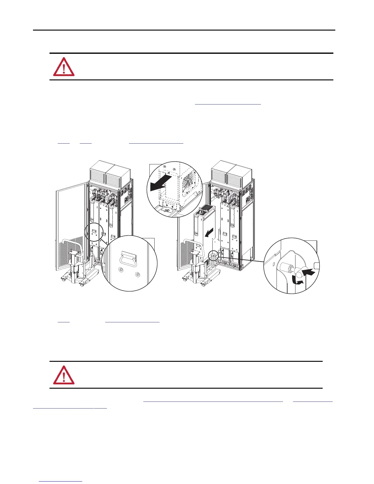
8. Use the handle that is attached to the power module to slowly extract it into the service cart tracks.
9. Lock the two anchor pins on the vertical supports of the service cart in to the power module chassis.
10. Unlock and remove the tie-in plate.
See
step 5 and step 6 figures in section Extract the Power Module for more information.
The service cart is disengaged from the cabinet.
11. Use the jackscrew to raise the bridge span above the cabinet floor.
12. Set the rear caster brakes to the OFF position.
See
step 7 figure in section Extract the Power Module for more information.
13. Move the service cart so the bridge span is clear of the cabinet floor.
14. Lower the carriage assembly to the lowest functional height.
The nearer the carriage assembly is to the ground, the lower the center of gravity is. Doing this increases the stability of the service cart when
a power module is loaded and in motion.
The service cart is ready to transport the module. See
Move the Power Module and the DC Precharge Module on page 16 and Unload, Load, and
Store the Power Module on page 19 for more information.
ATTENTION: Avoid equipment damage. Verify that the wire harnesses are secured and cleared from the extraction path when a power module is
removed. Failure to do so could result in damaged or sliced wire harnesses.
TIP To remove a DC precharge module skip steps 10...14 and continue with
Install the DCPC Module Lift on page 14.
It is recommended to mark the carriage trolley height for installation of the replacement power module. Recommended ways to mark include: masking
tape and a pencil. It is also recommended to use a bubble level, record the bubble positions, and make note of the slot that is used for the bridge span.
ATTENTION: Do NOT allow the carriage assembly to touch the floor until you are ready to park the cart.
8
8
9
2x

 Loading...


