18 Rockwell Automation Publication 750-IN105D-EN-P - June 2018
PowerFlex 750-Series Service Cart and DC Precharge Module Lift
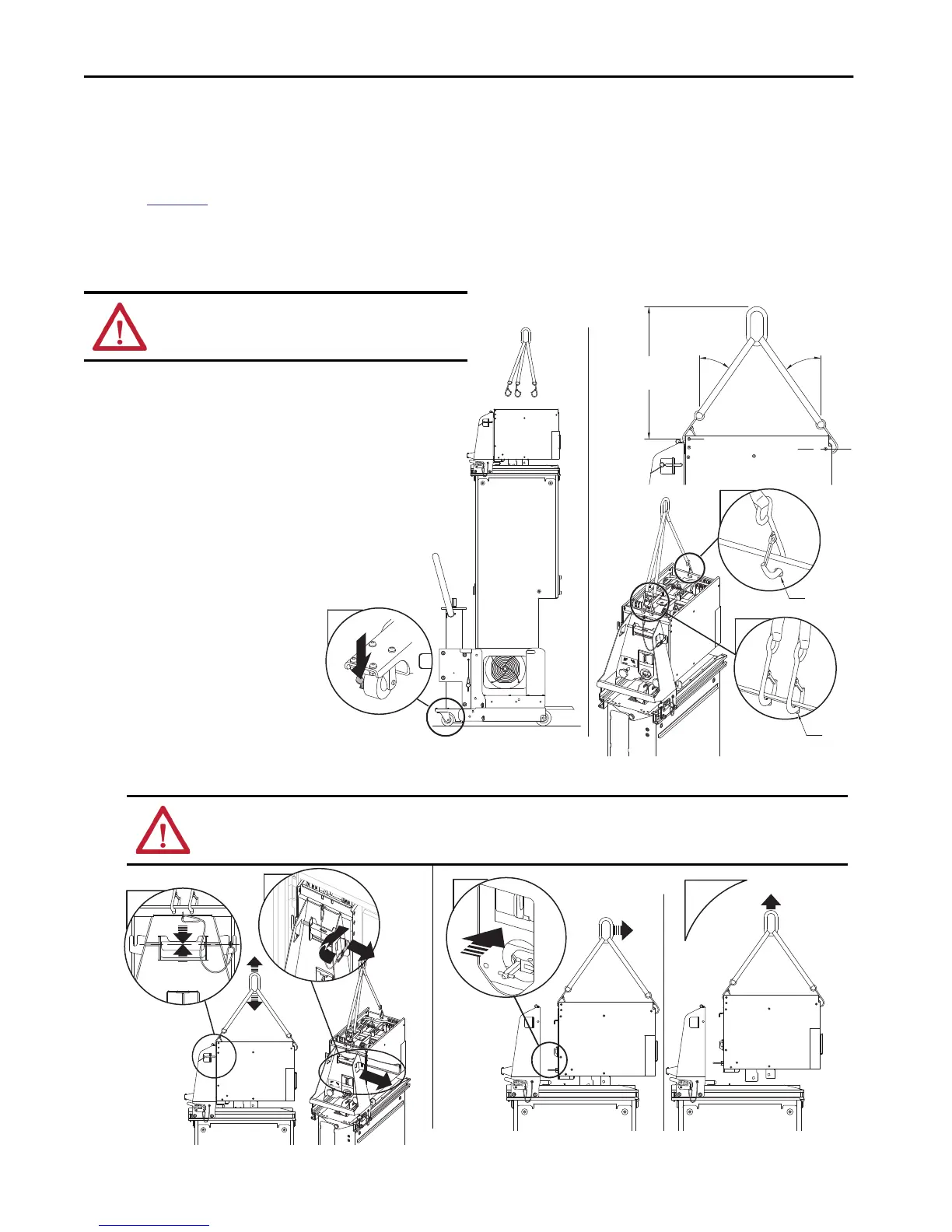
Unload or Load the DC Precharge Module from the DCPC Module Lift
Hoist the DC Precharge
For complete information on how to lift the DC precharge module, see Precharge Modules Unpacking and Lifting Instructions,
publication
750-IN103. The steps that are provided here can be used as a guide when the DC precharge module is removed from the DCPC
module lift. The steps that are provided here do not reflect the complete lifting procedure.
TIP The DC precharge module cannot be lifted straight up due to interference with the face connections when being removed from the DCPC module lift.
<45°
>199
(7.8)
Ø7
(0.3)
Ø10
(0.4)
<45°
2x
2
3
3
1. Move the cart with the DC precharge
module under the hoist.
2. Set the caster brakes to the ON
position.
3. Attach the sling (rated at 45 kg / 100 lb
or higher) to the front and rear lifting
holes of the DC precharge module.
4. Slowly raise the hoist to apply tension
to the sling until the DCPC module
lift locking bar can be removed.
5. Remove locking bar from the DC
precharge module and the DCPC
module lift.
6. Push the DC precharge module away
from the DCPC lift until the DC
precharge module flange and
disconnect switch are clear of
obstructions.
7. Complete the lift and place the DC
precharge module on a bench, pallet, or
workstation to be serviced or stored.
Do not store on the floor.
ATTENTION: Place the service cart rear casters in the ON position
before the hoist is connected. Failure to do so could result in
equipment damage.
.
ATTENTION: Avoid equipment damage. Make sure that the DC precharge module flange and disconnect switch are clear of obstructions before
the DC precharge module is lifted. See images.
ATTENTION: Avoid equipment damage. Make sure not to come in contact with the busbar on top of the power module.
4
b
5
a
b
6
7

 Loading...


