8 PowerFlex 755 On-Machine Packaged Drive
Rockwell Automation Publication 750-PC004B-EN-P - April 2019
EtherNet/IP Version Embedded Web Server
Out of box, the ETAP tap is configured to be a non-supervisor ring node and will respond to the default IP
address of 169.254.1.1. If your application does not require access to the taps diagnostic information or
configuration, no further action is required. Otherwise, set the IP address by using RSLinx Classic software, the
Studio 5000 Logix Designer application, or a BOOTP or DHCP server. See the Ethernet Tap Product information,
publication 1783-PC011
for more information on the 1783-ETAP adapter.
To access the internal web browser, open your computer’s internet browser and enter the IP address of the
desired packaged drive (for example, 192.168.1.1). From here, you are able to view parameter settings, device
status, and diagnostics from multiple tab views.
Set the PowerFlex 755 Frame 2 IP Address
This section provides instructions and information for setting the parameters to properly configure the
embedded EtherNet/IP adapter on the PowerFlex 755 drive. The On-Machine Packaged Drive connects to the
network through the1783-ETAP dual-port Ethernet adapter and supports DLR, linear, or star topology using the
ETH1 and ETH2 receptacles. The 24V DC control power must be present (via the CP receptacle) to configure the
1783-ETAP dual-port adapter.
Configuring the On-Machine PowerFlex 755 Ethernet IP Adapter
For PowerFlex 755 Embedded Ethernet IP detailed information, see the PowerFlex 755 Drive Embedded
EtherNet/IP Adapter User Manual, publication 750COM-UM001
. You must use the PowerFlex 20-HIM-C6S HIM to
configure the adapters IP address. The embedded EtherNet/IP adapter stores parameters and other information
in nonvolatile storage (NVS) memory. Access the adapter using the HIM to view and edit these parameters. After
the 1783-ETAP dual-port Ethernet adapter is configured, the following tools can be used to access drive
parameters that modify the adapter settings.
Using the PowerFlex 20-HIM-C6S HIM to Access Parameters
Your drive has an enhanced PowerFlex 20-HIM-C6S HIM, and it can be used to access parameters in the adapter.
1. Display the Status screen, which is shown on HIM power-up.
2. Use the or key to scroll to the Port in which the embedded EtherNet/IP adapter resides
(always Port 13).
3. To display the Jump to Parameter # entry popup box, press the PAR# soft key.
4. Use the numeric keys to enter the desired parameter number, or use the or soft key to scroll to the
desired parameter number.
For details on how to view and edit parameters, see the PowerFlex 20-HIM-A6/-C6S HIM (human interface
module) User Manual, publication 20HIM-UM001
.
Setting the Adapter IP Address
The PowerFlex 755 On-Machine Packaged Drive ships with its adapter thumb-wheel switches factory set to a
value of ‘999’. Based on this setting, Parameter 36 of Port 13 determines the source of the adapters Ethernet
IP address. When the adapter IP address switches are set to a value other than 001…254 or 888, Parameter
36 - [BOOTP] determines the source for the adapter node address. By default, the embedded EtherNet/IP
adapter on a Frame 2 PowerFlex 755 is configured to set its IP address, subnet mask, and gateway address by
using a BOOTP server. The On-Machine Packaged Drive cannot use a BOOTP server to set the node address
because of the 1783-ETAP dual-port Ethernet adapter, see Using Adapter Parameters
on page 8.
Using Adapter Parameters
By default, the adapter is configured to use a BOOTP server as the source for the adapter IP address, subnet
mask, and gateway address. To use adapter parameters instead, you must first disable BOOTP by using
Parameter 36 - [BOOTP]. Then set the associated adapter parameters as described in the following
subsections.
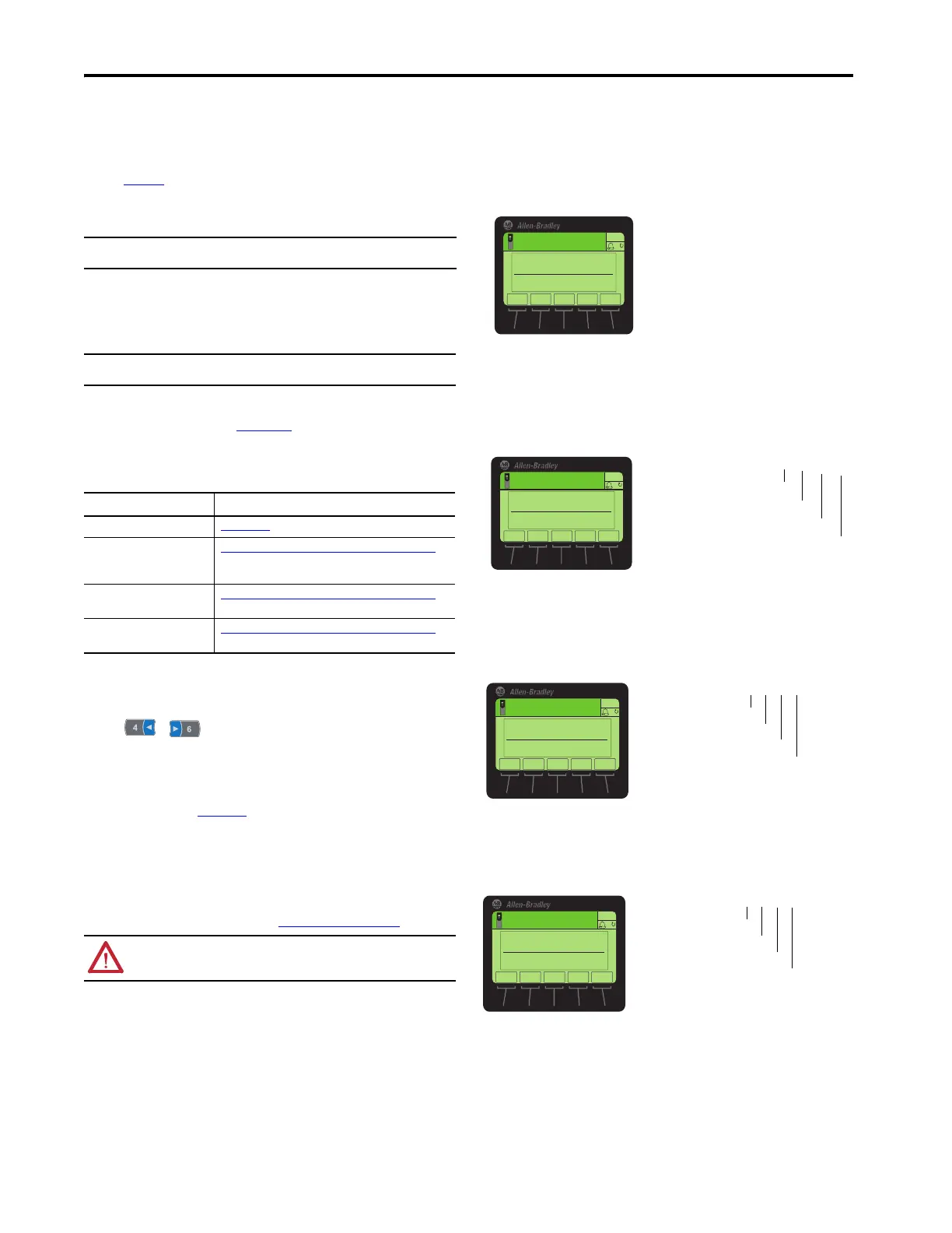
Disable the BOOTP Feature or Change the Source for the Node Address
1. Set the value of Parameter 36 - [BOOTP] to ‘0’ (Disabled).
2. Cycle power to the drive to reset the adapter or by using the HIM Reset Device function that is located in the
DIAGNOSTIC folder of the drive.
3. Set the IP address, subnet mask, and gateway address by using adapter parameters. Perform the steps in the
following subsections.
Set the IP Address
1. Verify Parameter 36 - [BOOTP] is set to ‘0’ (Disabled).
2. Set the value of Parameters 38 - [IP Addr Cfg 1] through 41 - [IP Addr Cfg 4] to a unique IP address.
3. Cycle power to the drive to reset the adapter or by using the Reset Device function of the HIM, located in the
DIAGNOSTIC folder for the drive.
– The ENET status indicator is steady green or updates green if the IP address is correctly configured.
Set the Subnet Mask
1. Verify Parameter 36 - [BOOTP] is set to ‘0’ (Disabled).
2. Set the value of Parameters 42 - [Subnet Cfg 1] … Parameter 45 - [Subnet Cfg 4] to the desired value
for the subnet mask.
3. Cycle power to the drive to reset the adapter or by using the Reset Device function of the HIM located in the
DIAGNOSTIC folder for the drive.
Set the Gateway Address
1. Verify Parameter 36 - [BOOTP] is set to ‘0’ (Disabled).
2. Set the value of Parameters 46 - [Gateway Cfg 1] … Parameter 49 - [Gateway Cfg 4] to the IP address
of the gateway device.
3. Cycle power to the drive to reset the adapter or by using the HIM Reset Device function that is located in the
DIAGNOSTIC folder of the drive.
IMPORTANT When editing a parameter the default User Name is Administrator and no password. The
user should set the password to a unique value for authorized personnel.
IMPORTANT If you use BOOTP or DHCP to set the IP address, only the IP address of the 1783-ETAP
module is set. It does not affect the setting for the PowerFlex drive.
Tool Reference
PowerFlex 20-HIM-C6S HIM 20HIM-UM001
Connected Components
Workbench™ software, version 1.02
or later
http://compatibility.rockwellautomation.com/Pages/ home.aspx
, or
online help (installed with the software)
DriveExplorer™ software, version
6.01 or later
http://compatibility.rockwellautomation.com/Pages/ home.aspx
, or
online help (installed with the software)
DriveExecutive™ software, version
5.06 or later
http://compatibility.rockwellautomation.com/Pages/ home.aspx
, or
online help (installed with the software)
ATTENTION: Do not cycle 400/480V AC power more frequently than one cycle every 1 minute.
Failure to comply will result in serious equipment damage.
ESC
ENTER
Stopped
0.00 Hz
AUTO
F
▲▼
Edit BOOTP
Disabled0
0<<1
Default = 0.0.0.0
255.255.255.2
[IP Addr Cfg 1]
[IP Addr Cfg 2]
[IP Addr Cfg 3]
[IP Addr Cfg 4]
Edit IP Addr Cfg 1
0
0 << 255
ESC
ENTER
Stopped
0.00 Hz
AUTO
F
Default = 0.0.0.0 255.255.255.2
[Subnet Cfg 1]
[Subnet Cfg 2]
[Subnet Cfg 3]
[Subnet Cfg 4]
Edit Subnet Cfg 1
0
0<<255
ESC
ENTER
Stopped
0.00 Hz
AUTO
F
Default = 0.0.0.0 255.255.255.2
[Gateway Cfg 1]
[Gateway Cfg 2]
[Gateway Cfg 3]
[Gateway Cfg 4]
Edit Gateway Cfg 1
0
0 << 255
ESC
ENTER
Stopped
0.00 Hz
AUTO
F

 Loading...


