DC (10–30V) Output Module10
Publication 1771-IN036C-EN-P - July 2002
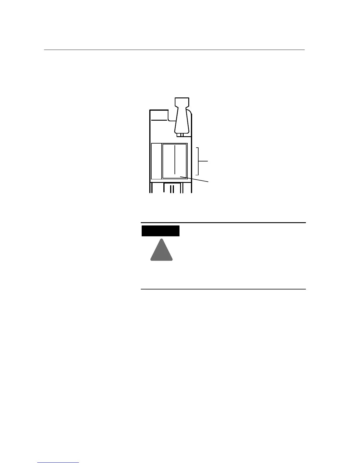
The module has 32 status indicators on the module front plate. These
represent the control status of the outputs. Each indicator is lit when
its corresponding output is energized. An additional indicator is
provided to indicate a blown fuse condition.
00
01
02
03
04
05
06
07
10
11
12
13
14
15
16
17
Status Indicators (red)
00
01
02
03
04
05
06
07
10
11
12
13
14
15
16
17
FUSE
Fuse Blown Indicator
10436ĆI
To replace a blown fuse, proceed as follows:
!
ATTENTION
Remove power from the 1771 I/O chassis
backplane and field wiring arm before removing
or installing an I/O module.
• Failure to remove power from the backplane or
wiring arm could cause module damage,
degradation of performance, or injury.
• Failure to remove power from the backplane
could cause injury or equipment damage due to
possible unexpected operation.
1. Turn off power to the chassis.
2. Remove the module from the I/O chassis.
3. Remove the blown fuse from the fuse holder (accessible through
side cover), and replace it with a 4A, 250V normal blow fuse.
4. Reinsert the module into the I/O chassis.
5. Turn on power to the chassis.
Interpreting the Status
Indicators
Replacing the Fuses
 Loading...


