DC (10–30V) Output Module8
Publication 1771-IN036C-EN-P - July 2002
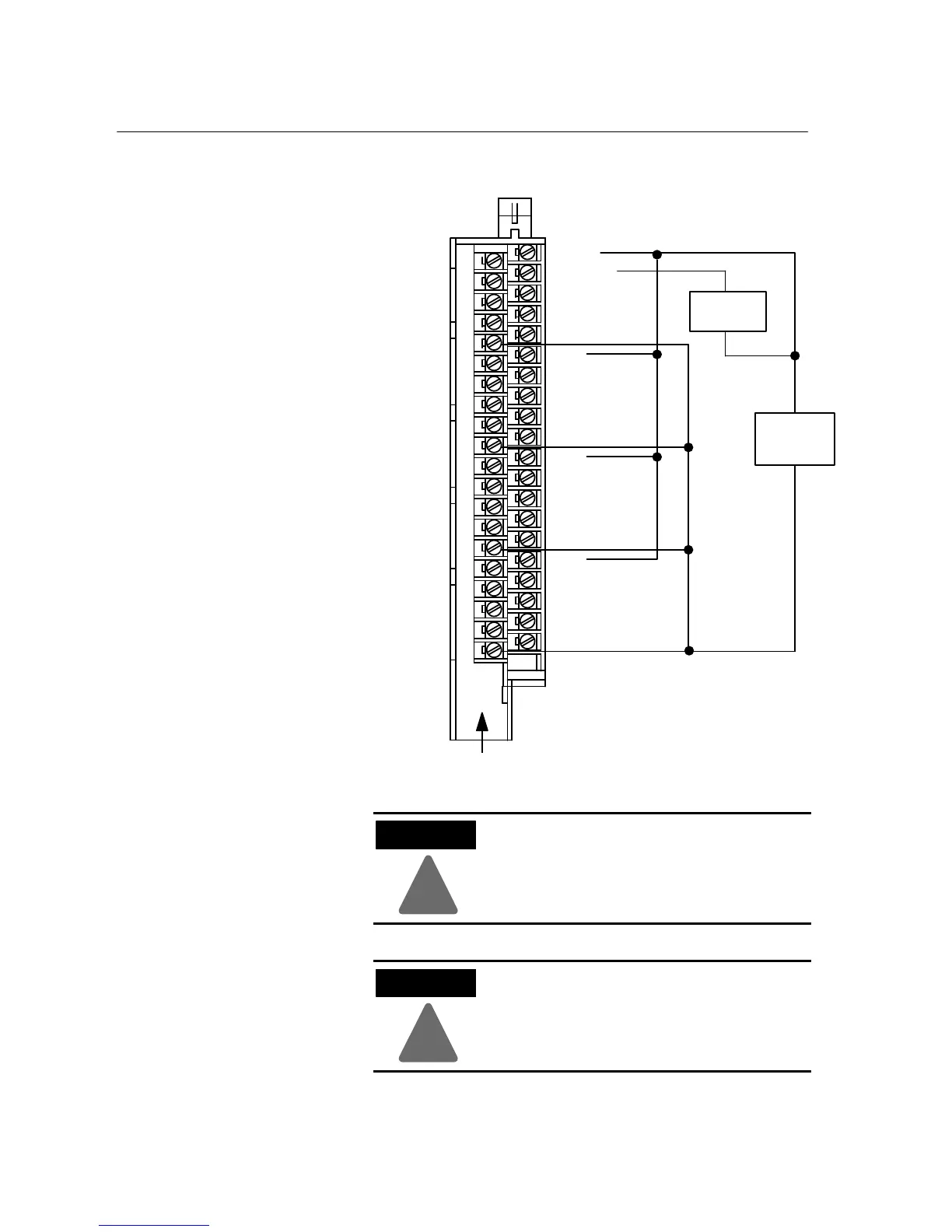
Connection Diagram for the 1771ĆOVN/B DC Output Module
Output 0
Output 2
Output 4
Output 6
Common 0
Output 10
Output 12
Output 14
Output 16
Common 1
Output 0
Output 2
Output 4
Output 6
Common 2
Output 10
Output 12
Output 14
Output 16
Common 3
+dc
Output 1
Output 3
Output 5
Output 7
+dc
Output 11
Output 13
Output 15
Output 17
+dc
Output 1
Output 3
Output 5
Output 7
+dc
Output 11
Output 13
Output 15
Output 17
+
Ć
dc
Supply
dc Output
Device
Ć
+
Note: Terminals on the left are even
numbered (2 thru 40) , and terminals
on the right are odd numbered
(1 thru 39).
2
4
6
8
10
12
14
16
18
20
22
24
26
28
30
32
34
36
38
40
Actual wiring runs in this direction.
10435ĆI
Terminals 1 through 20 represent module group 1.
Terminals 21 through 40 represent module group 2.
Terminals 10, 20, 30 and 40 are dc common and
terminals 1, 11, 21, and 31 are dc power.
If multiple power sources are used, do not exceed the specified isolation voltage.
!
ATTENTION
Observe proper polarity, as indicated in the
connection diagram with dc power connections.
Reverse polarity, or application of ac voltage,
could damage the module.
!
ATTENTION
Miswiring or shorting the output terminals will
cause permanent damage to this module.
 Loading...


