21
Maintenance
Control Cable Adjustment, PFO
Check the operation of the control lever to make sure it
moves smoothly and will return to BRAKE-ON position.
The control lever will stay in BRAKE-OFF or FREESPOOL
position, as they are both detent positions. Make sure the
control lever does not hit the housing at the end of its travel.
Check that the positions of the control lever align with the
position indicators on the control lever decal.
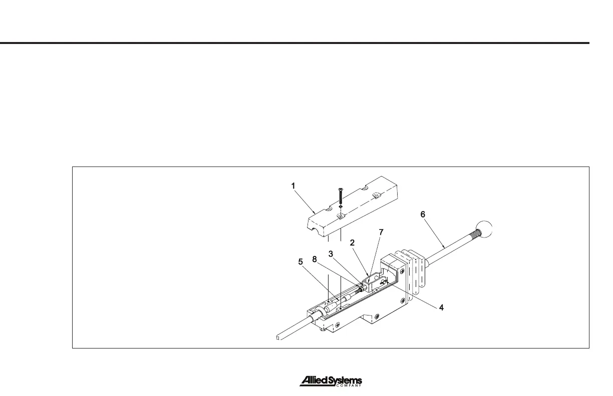
Figure 14 - Control Cable Adjustments
1. Access Cover
2. Clevis
3. Tall Nut
4. Cotter Pin and Link Pin
5. Control Cable
6. Control Lever
7. Screw
8. Jam Nut
9. Screw
Remove the access cover on the housing to make
adjustments. Loosen the jam nut that keeps the adjustment
nut and clevis from turning. Remove the cotter pin and link
pin from the clevis. Turn the adjustment nut and clevis
to adjust the length of the control cable. Use the link pin
and cotter pin to connect the clevis to the control handle
again and check the operation. When the adjustment is
complete, tighten the jam nut and install the access cover.