Do you have a question about the Allied Telesis AT-8012M and is the answer not in the manual?
Specifies compliance with Radio Frequency Interference standards.
Details compliance with Electromagnetic Interference Immunity standards.
Lists compliance with various electrical safety standards.
Specifies compliance with laser safety regulations.
Details FCC Part 15 Class A radiated energy compliance.
Compliance with Canadian Interference-Causing Equipment Regulations.
Specifications for fiber optic port connectivity and cabling.
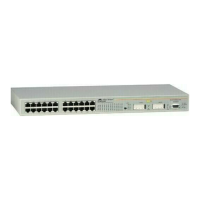
Details on RJ-45 port specifications, speed, and duplex mode.
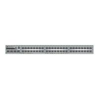
Specifications for Gigabit Ethernet RJ-45 ports.
Information on adding Gigabit ports using optional GBIC modules.
Details on adding optional expansion or stacking modules.
Explains the function of port status indicators and mode selection.
Lists essential safety warnings before proceeding with installation.
Guidelines for choosing an appropriate installation location.
Information on cabling requirements and distances.
Steps for safely removing the switch from its packaging.
Procedures for mounting the switch in a standard 19-inch rack.
Instructions for adding optional GBIC, expansion, or stacking modules.
Steps to install the optional AT-RPS3004 redundant power supply unit.
Connect data cables and apply power to the switch.
Guide for connecting DC power to compatible switch models.
How to establish a serial console connection for management.
Instructions for registering the product for warranty coverage.
| Brand | Allied Telesis |
|---|---|
| Model | AT-8012M |
| Category | Switch |
| Language | English |