Do you have a question about the Allied Telesis AT-8024 and is the answer not in the manual?
Details electrical safety standards like UL60950 and EN60950.
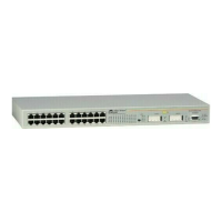
Describes the AT-8012M switch, its ports, and features.
Describes the AT-8012M-QS switch, its ports, and features.
Describes the AT-8016F/xx series switches, their ports, and features.
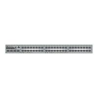
Describes the AT-8024 switch, its ports, and features.
Describes the AT-8024GB switch, its ports, and features.
Lists crucial safety precautions before installation.
Provides guidelines for choosing a suitable installation location.
Covers cabling specifications for twisted pair and fiber optic ports.
Step-by-step guide for mounting the switch in a 19-inch rack.
Instructions for installing GBIC modules in AT-8024GB switches.
Guide for installing expansion or stacking modules on compatible switches.
Instructions for installing the optional redundant power supply unit.
Covers connecting data cables and applying power to the switch.
Specific instructions for wiring DC-powered switch models.
Steps to establish a local management connection via RS-232.
| Ports | 24 |
|---|---|
| Uplink Ports | 4 |
| Layer | Layer 2 |
| Power Supply | Internal |
| MAC Address Table Size | 8K |
| VLANs | 256 |
| Jumbo Frame Support | Yes |
| Management | Web, CLI |
| Dimensions | 440 x 44 x 220 mm |
| Operating Temperature | 0°C to 50°C |
| Storage Temperature | -40°C to 70°C |
| Humidity | 10% to 90% (non-condensing) |