Overview
44
Collapsed
Backbone - Hub
Topology
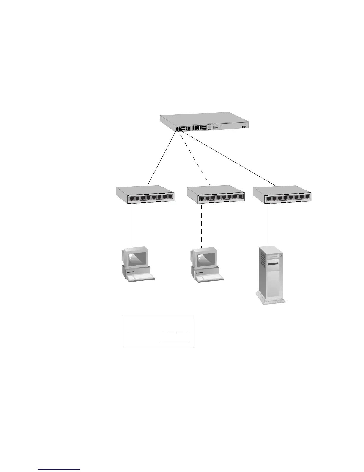
In the topology illustrated in Figure 15, an AT-8024 connects together
10/100 Mbps Ethernet hubs. This type of topology is often referred to as
a collapsed backbone topology. The switch functions as the focal point
of the network by acting as a bridge between the different workgroups.
The switch transfers an Ethernet frame from hub to hub only when the
destination end-node for the frame is on a different hub than the end-
node that originated the frame. This reduces the amount of unnecessary
data traffic in each workgroup, freeing up bandwidth and improving
network performance.
Figure 15. Collapsed Backbone - Hub Topology
L
i
n
k
M
o
d
e
L
i
n
k
M
o
d
e
1
0
0
F
U
L
L
A
C
T
M
O
D
E
C
O
L
F
A
U
L
T
M
A
S
T
E
R
P
W
R
AT-8024
10
Base
-
T
/100
Base-TX F
ast Eth
ernet Switc
h
R
S
-
2
3
2
T
E
R
M
I
N
A
L
P
O
R
T
54
3
2
1
6
7
8
54
3
2
1
6
7
8
54
3
2
1
6
7
8
Legend
10 Mbps
100 Mbps
AT-8024 Fast
Ethernet Switch
Ethernet
Hubs