Installation & Safety Guide 9
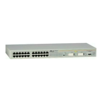
Figure 2: AT-8624PoE front and rear panel with AC power inlet
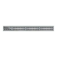
Figure 3: AT-8648T/2SP front and rear panel with AC power inlet
7. Check that the PWR LED on the switch’s front panel is green.
If the PWR (power) LED fails to light, refer to the AT-8600 Series Hardware
Reference for troubleshooting information.
8. Connect the data cables.
Make sure each cable connection is secure. The switch can now process
basic Layer 2 switching functions.
 Loading...