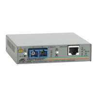
Overview
4
Link Test/MissingLink Button
The Link Test/MissingLink button allows you to perform a link test on the
ports on the media converter. This button also allows you to activate the
MissingLink feature on the unit. Both features are describe in the following
section.
Note
After using the Link Test/MissingLink button to select between the two
settings, you must reset the media converter by powering OFF then
powering ON the unit
Link Test. The link test is a fast and easy way for you to test the connections
between the ports on the media converter and the nodes that are connected to
the ports. If a network problem occurs, you can perform a link test to
determine which port is experiencing a problem, and be able to focus on the
port and end-node where the problem resides.
A link test is performed when the button is in the LNK TST (OUT) position.
For instructions on performing a link test, refer to “Troubleshooting” on page
15.
Note
Leaving the media converter in the LNK TST (OUT) position will not
interfere with the units ability to pass network traffic. Leaving the unit
in this position will ensure that after a network recovery, the media
converter will automatically resume passing network traffic.
MissingLink. The MissingLink feature enables the fiber optic ports on the
media converter to pass the “Link” status of their connections to each other.
When the media converter detects a problem with one of the ports, such as the
loss of connection to an end-node, the media converter shuts down the
connection to the other port, thus notifying the node that the connection has
been lost.
For example, if the twisted pair cable to the 100Base-TX port on the media
converter were to fail, the media converter would respond by dropping the link
on the 100Base-FX fiber optic port. In this way, the media converter notifies
the end-node connected to the fiber optic port that the connection on the
twisted pair port has been lost. If the failure had started with the fiber optic
cabling, the unit would drop the link to the twisted pair port.

 Loading...