EasyManua.ls Logo

Allied Telesis AT-MMC6005 - User Manual

Allied Telesis AT-MMC6005
58 pages
Print Icon
To Next Page IconTo Next Page
Loading...
613-002395 Rev. A
AT-MMC6000 Series
VDSL Mini Media Converters
AT-MMC6005
AT-MMC6005-E
AT-MMC6006
Installation Guide

Table of Contents

Questions and Answers

  • D
    David FlemingAug 2, 2025
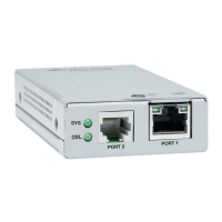
    How to fix Allied Telesis AT-MMC6005 Media Converter SYS LED off?
    • R
      Robert HansonAug 2, 2025
      If the SYS LED on your Allied Telesis Media Converter is off, it indicates the unit isn't receiving power. Here's what you should do: * Ensure the power cord is properly connected to both the power source and the DC connector on the back of the media converter. * Test the power outlet by plugging in another device to confirm it's working. * Try a different power adapter of the same type that came with your media converter. * Check that the voltage from the power source matches the required levels for your region. If these steps don't resolve the issue, try power cycling the unit. If the problem persists, return the unit to Allied Telesis.
  • D
    Dylan GonzalezAug 22, 2025
    What to do if Allied Telesis AT-MMC6005 DSL LED is off?
    • D
      David MitchellAug 22, 2025
      If the DSL LED on your Allied Telesis Media Converter is off, it indicates that the DSL subsystem has stopped responding. You can try to resolve this by power cycling the media converter. Also, check the copper connection. Note that the DSL LED will turn off if the local unit has SML enabled, and the copper connection is lost.
  • P
    Penny LaneNov 11, 2025
    What to do if Allied Telesis AT-MMC6005 COPPER P1 L/A LED is off?
    • R
      Rita WilsonNov 11, 2025
      If the twisted-pair port's COPPER P1 L/A LED is off on your Allied Telesis Media Converter, it means a link to the end node couldn't be established. To resolve this: 1. Make sure the end node connected to the twisted-pair port is powered on and functioning correctly. 2. Check that the twisted-pair cable is securely plugged into both the media converter and the remote end node. 3. Confirm that you're using the correct twisted-pair cable for the port. 4. Try connecting a different end node with a different cable to see if a link can be established. If it works, the issue is with the original cable or end node. 5. Ensure the twisted-pair cable is shorter than 100 meters (328 feet). 6. Verify the end node is set to Auto-Negotiate. 7. Use the appropriate category of twisted-pair cable: ...

Summary

Electrical Safety and Emissions Standards

Federal Communications Commission Interference Statement

Details FCC compliance, interference statement, and rules for digital devices.

European Union Restriction of the Use of Certain Hazardous Substances (RoHS) in Electrical and Electronic Equipment

Explains RoHS compliance for the product and Allied Telesis's conformance process.

Emissions, Immunity and Electrical Safety Standards

Lists standards for RFI emissions, EMC immunity, and electrical safety compliance.

Translated Safety Statements

Indicates availability of translated safety statements on the Allied Telesis website.

Preface

Document Conventions

Explains document conventions like notes, cautions, and warnings.

Contacting Allied Telesis

Provides contact information and support services for Allied Telesis.

Chapter 1: Product Description

Introduction

Introduces the AT-MMC6000 Series VDSL Mini Media Converters and their purpose.

Summary of Features

Lists the key hardware and software features of the AT-MMC6000 Series media converters.

Overview

Describes the typical use cases and installation scenarios for the media converter system.

Location of Components

Illustrates and identifies the front and rear panel components of the AT-MMC6000 Series.

VDSL Line Port

Describes the VDSL line port, including connectors, distance, and frequency capabilities.

VDSL2 Profiles and Settings

Explains how to configure VDSL2 profiles using DIP switches on the Provider unit.

10;100;1000 Mbps Twisted Pair Ethernet Port

Describes the Ethernet port's specifications, auto-negotiation, and MDI/MDI-X capabilities.

Half- and Full-duplex Mode

Explains duplex modes and how the media converter uses auto-negotiation for Ethernet link setup.

Status LEDs

Details the meaning and states of the System (SYS) and DSL LEDs.

DIP Switches

Explains the function of DIP switches for configuring the unit as Subscriber/Provider and VDSL2 profiles.

Smart MissingLink (SML)

Describes the SML feature for network fault detection and troubleshooting.

DC Power Supply Input Port

Details the DC power input port and the function of the external AC/DC power adapter.

Chapter 2: Installation

Installation Safety Precautions

Outlines essential safety precautions to follow before installing the media converters.

Selecting a Site for the Media Converter

Provides guidelines for choosing a suitable location for installing the media converter.

Cables Not Included

Lists the cables required for connecting the media converter and notes they are not included.

Unpacking the Media Converter

Details the steps for unpacking the media converter and verifying its accessories.

Installing the Subscriber Unit

Guides through desktop and wall-mounting installation for the Subscriber unit.

Using the Subscriber Unit on a Desktop

Instructions for desktop placement of the Subscriber unit, including attaching rubber feet.

Wall-Mounting the Subscriber Unit

Refers to Appendix B for instructions on wall-mounting the Subscriber unit.

Setting the Subscriber Unit DIP Switches

Explains how to configure the Subscriber unit using DIP switch 1 for mode and DIP switch 5 for SML.

Cabling the Subscriber Unit

Provides instructions for connecting Ethernet and DSL cables to the Subscriber unit.

Powering On the Subscriber Unit

Details the procedure for connecting power to the Subscriber unit and checking the SYS LED.

Installing the Provider Unit

Covers installation options for the Provider unit, including desktop, wall, and rack mounting.

Using the Provider Unit on a Desktop

Instructions for desktop placement of the Provider unit, including attaching rubber feet.

Wall-Mounting the Provider Unit

Refers to Appendix B for instructions on wall-mounting the Provider unit.

Rack Mounting the Provider Unit

Refers to the AT-MMCR18 Chassis Installation Guide for rack mounting.

Setting the Provider Unit DIP Switches

Explains how to configure Provider unit DIP switches for mode, VDSL2 profile, and SML.

Cabling the Provider Unit

Provides instructions for connecting Ethernet and DSL cables to the Provider unit.

Powering On the Provider Unit

Details the procedure for connecting power to the Provider unit and checking the SYS LED.

Chapter 3: Troubleshooting

Appendix A: Technical Specifications

Physical Specifications

Provides physical dimensions and weight of the media converter.

Environmental Specifications

Lists operating and storage temperature, humidity, and altitude specifications.

Power Specifications

Details the input voltage and current requirements for the media converter.

Safety and Electromagnetic Emissions Certifications

Lists safety, emissions, immunity, and environmental compliance certifications.

RJ45 Connector and Port Pinouts

Provides pinout details for the RJ45 Ethernet connector in MDI and MDI-X configurations.

Appendix B: AT-MMCWLMT Kit Installation

AT-MMCWLMT Kit Contents

Lists the components included in the AT-MMCWLMT kit for wall mounting.

Attaching the Brackets to the Media Converter

Instructions on how to attach the wall-mounting brackets to the media converter.

Marking the Screw Hole Locations

Details how to position the unit and mark screw hole locations on the wall.

Securing the Media Converter to the Wall

Explains the final step of securing the media converter to the wall using mounting screws.

Allied Telesis AT-MMC6005 Specifications

General IconGeneral
Device TypeMedia Converter
ModelAT-MMC6005
Connector TypeRJ-45, SC
Wavelength1310 nm
Data Transfer Rate100 Mbps
Power SupplyExternal
Fiber TypeMultimode
Operating Temperature0°C to 40°C (32°F to 104°F)
Storage Temperature-40°C to 70°C
Humidity5 to 90% (non-condensing)

Related product manuals