17
Chapter 1
Product Description
This chapter describes the following media converters:
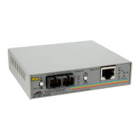
AT-MMC6005
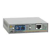
AT-MMC6005-E
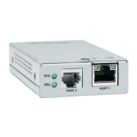
AT-MMC6006
This chapter contains the following sections:
“Introduction” on page 18
“Summary of Features” on page 19
“Overview” on page 20
“Location of Components” on page 21
“Feature Description” on page 22
 Loading...