AT-MMC6000 Series Installation Guide
21
Location of Components
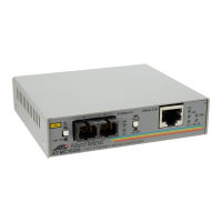
Figure 2 illustrates the front panel of the AT-MMC6005.
Figure 2. AT-MMC6005 Front Panel
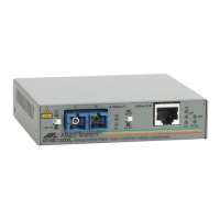
Figure 3 illustrates the front panel of the AT-MMC6006.
Figure 3. AT-MMC6006 Front Panel
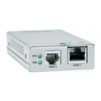
Figure 4 illustrates the AT-MMC6000 Series rear panel which is used on
all the models. Switches are shown in factory default positions.
Figure 4. AT-MMC6000 Series Rear Panel
Ethernet Port
DSL LED
VDSL2 Line Port
Ethernet Port
L/A LED
Ethernet Port
Duplex/Collision
LED
System LED
DSL LED
Ethernet Port
L/A LED
Ethernet Port
Duplex/Collision
LED
System LED
Ethernet Port
VDSL2 Line Port
DC Power Supply Port
DIP Switches
 Loading...