EasyManua.ls Logo

Allis-Chalmers HD-4 - Valve Tappet Clearance

Allis-Chalmers HD-4
80 pages
Print Icon
To Next Page IconTo Next Page
To Previous Page IconTo Previous Page
Loading...
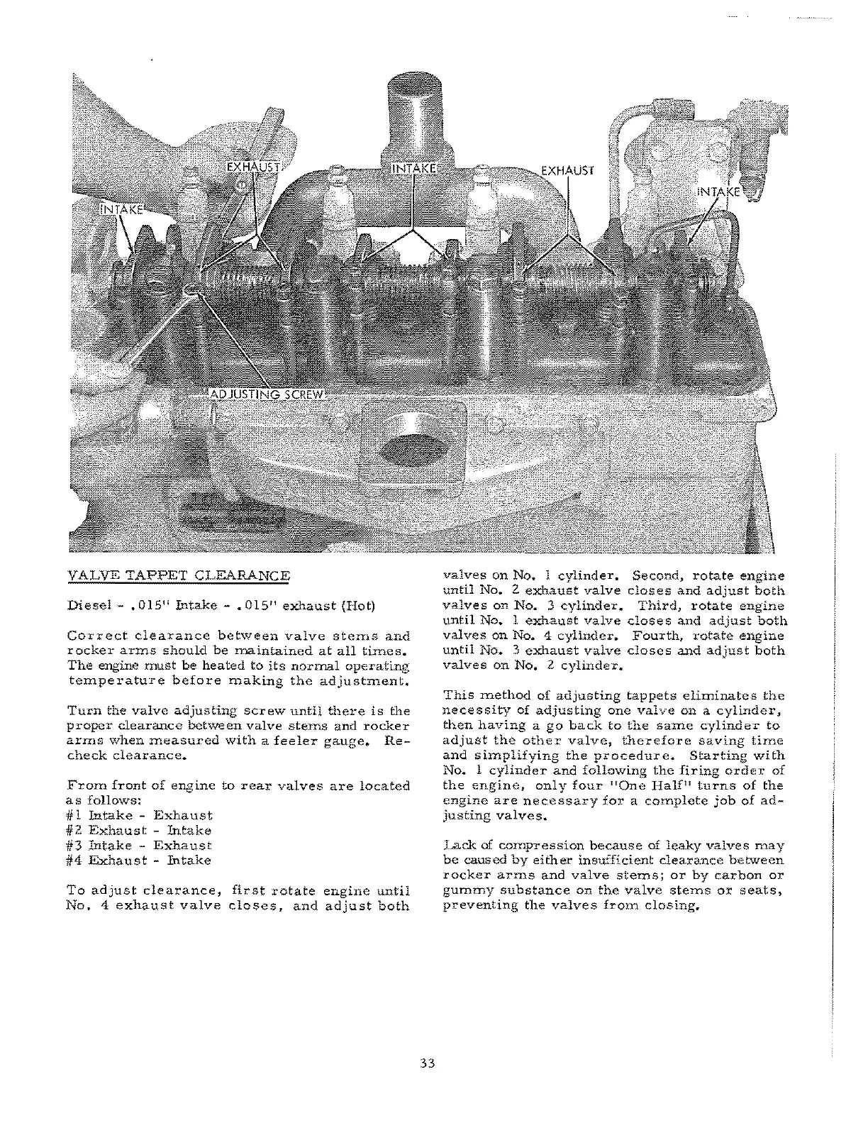
VALVE
TAPPET
CLEARANCE
Diesel
-
.015"
Intake
- •
015"
exhaust
(Hot)
Correct
clearance
between
valve
sterns
and
rocker
arms
should
be
maintained
at
all
thnes.
The
engine
must
be
heated
to
its
normal
operating
temperature
before
making
the
adjustment.
Turn
the
valve
adjusting
SCrew
until
there
is
the
proper
clearance
between
valve
ste:rns
and
rocker
arms
when
measured
with
a
feeler
gauge.
Re-
check
clearance.
From
front
of
engine
to
rear
valves
are
located
as
follows:
# I
Intake
-
Exha
us
t
*2
Exhaust
-
Intake
If
3
Intake
-
Exha
us
t
1/4
Exhaust
-
Intake
To
adjust
clearance,
first
rotate
engine
until
No.4
exhaust
valve
closes~
and
adjust
both
33
valves
on
No.
1
cylinder..
Second,
rotate
engine
until
No.
2
exhaust
valve
closes
and
adjust
both
valves
on
No
..
3
cylinder.
Third,
rotate
engine
until
No.
1
exhaust
valve
close
s
and
adjust
both
valves
on
No.
4
cylinder.
Fourth,
rotate
engine
until
No.
3
exhaust
valve
closes
and
adjust
both
valves
on
No* 2
cylinder
..
This
method
of
adjusting
tappets
eliminates
the
necessity
of
adjusting
one
valve
on
a
cylinder,
then
having
a
go
back
to
the
Same
cylinder
to
adjust
the
other
valve,
therefore
saving
time
and
simplifying
the
procedure.
Starting
with
No.
1
cylinder
and
following
the
£iring
order
of
the
engine,
only
four
!tOne
Halfl!
turns
of
the
engine
are
necessary
for
a
complete
job
of
ad-
justing
valves.
l...ack of
co:rnpression
because
of
leaky
valves
may
be
caused
by
either
insufficient
clearance
between
rocker
arms
and
valve
sterns;
or
by
carbon
or
gummy
substance
on
the
valve
stell1S
oX'
seats,
preventing
the
valves
frorn
closing.