F:':'NGI~~HOODAND HOODSUPPORT
-0
Removal
The hood and hood suppc·rt IndY be' removed
together if the, capscrcws, attaching the hood
to the radiator are removed and the two
short capscrews, spal..ers,' the oue long cap-
screw and spacer are removed from the lower
portion of the hood support at the crank end
of the engine. Remove the tail light from the
hood support.
If the"hood alone is to be removed, the bolts
Inust be removed from the hood at the top of
the hood support •
.ELili...,ASSEMBLY
Removal
Loosen the gene rato:l."<'.adrnove it toward
engine in order to rt::nove tension h'orn the
fan belt. Remove the air cleaner and the
instrwnent box from the fan shaft bracket.
Remove the carburetor dir inlet pipe and
bracket from the cylind~r head. Remove
the four nuts attaching JQ~_fanshaft brackets
to the cylinder head. .. -.-- .
PULLING FAN~·· -~. __ ...•
To remove the fan
h-OlU the shaft, it is neces-
sary to remove the £.'Ulbnicket hon'l the bear-
ings and attach the OTC puller as shovmusing
a 1/2" x 2"spacer equipped with a 60° center
between the puller screw and the fan shaft.
The pulley may be removed irom the shc-.fi:
with the same tool. This wo;-k>:naybe done
more satisfactorily if a presE is available"
Inspection
Inspection of th{;
fiiIl may b~ acco!'l:l~li~~(>d
G - 7
without removing it from the engine. Check
the bearings for wear and roughness. They
should not be rough or worn more than .006'1.
Check the fan belt sheave contact surface for
wear caused by the fan belt. If the wear in-
dicates that the surfaces are curved or that
the belt bottoms in the sheave, the sheave
should be replaced. The fan shaft should be
straight. Check fan blades fa r loose rivets
or cracks.
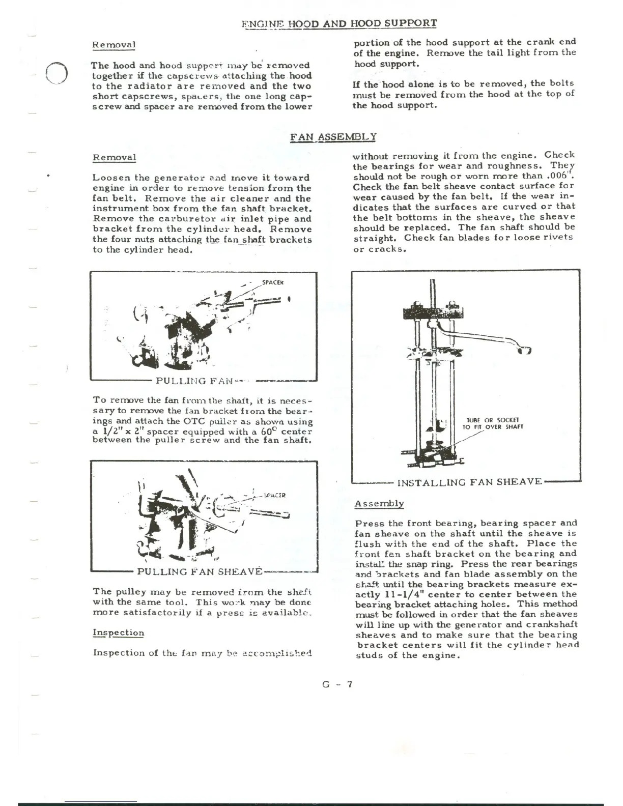
lUBE OR SOCKET
TO FIT OVER SHAfT
INSTALLING FAN SHEAVE
Assembly
Press the front bearing, bearing spacer and
fan sheave on the shaft until the sheave is
flush with the end of the shaft. Place the
front fan shaft bracket on the bearing and
instal: the snap ring. Press the rear bearings
and '::>racketsand fan blade as sembly on the
st.3!.f: until the bearing brackets measure ex-
actly 11-1/4" center to center between the
bearing bracket attaching holes. This method
must be followed in order that the fan sheaves
will line up with the generator and crankshaft
sheaves and to make sure that the bearing
bracket centers will fit the cylinder head
studs of the engine.