FMI-B
FMI-S
Bedienungsanleitung
Operation manual
Notice d’utilisation
Instrucciones de servcio
Istruzioni per l’uso
www.alluris.de
Page 28 of 34
5.2.3. Data cable for digital I/O’s
Cable with Hirose-socket (part no.: FMI-934SO):
• 3VDC power supply
• Digital input
• Trigger signal for synchronized measuring frequency
• Digital output (setting via FMI_Analyze)
• Digital limit/overload output
Cable assignment wire end
Colour Assignment Function
1 Weiss / White Supply 3VDC
3VDC supply
2 Braun /Brown GND
3 Grün / Green DIGIN1 Digital input
4 Gelb / Yellow TRIGGER_OUT(C) Trigger signal
measuring
frequency
5 Grau / Grey TRIGGER_OUT(E)
6 Orange / Orange DIGOUT1(C)
Digital output
setting via
FMI_Analyze
7 Blau / Blue DIGOUT1(E)
8 Rot / Red DIGOUT2(C)
9 Schwarz / Black DIGOUT2(E)
10 Violett / Violet DIGOUT3(C)
11 Schwarz-Weiss / Black-White DIGOUT3(E)
12 Rot-Weiss / Red-White LIMIT_MAX(C)
Digital limit/
overload output
13 Weiss-Grün / White-Green LIMIT_MAX(E)
14 Braun-Weiss / Brown-White LIMIT_MIN(C)
15 Weiss-Gelb / White-Gelb LIMIT_MIN(E)
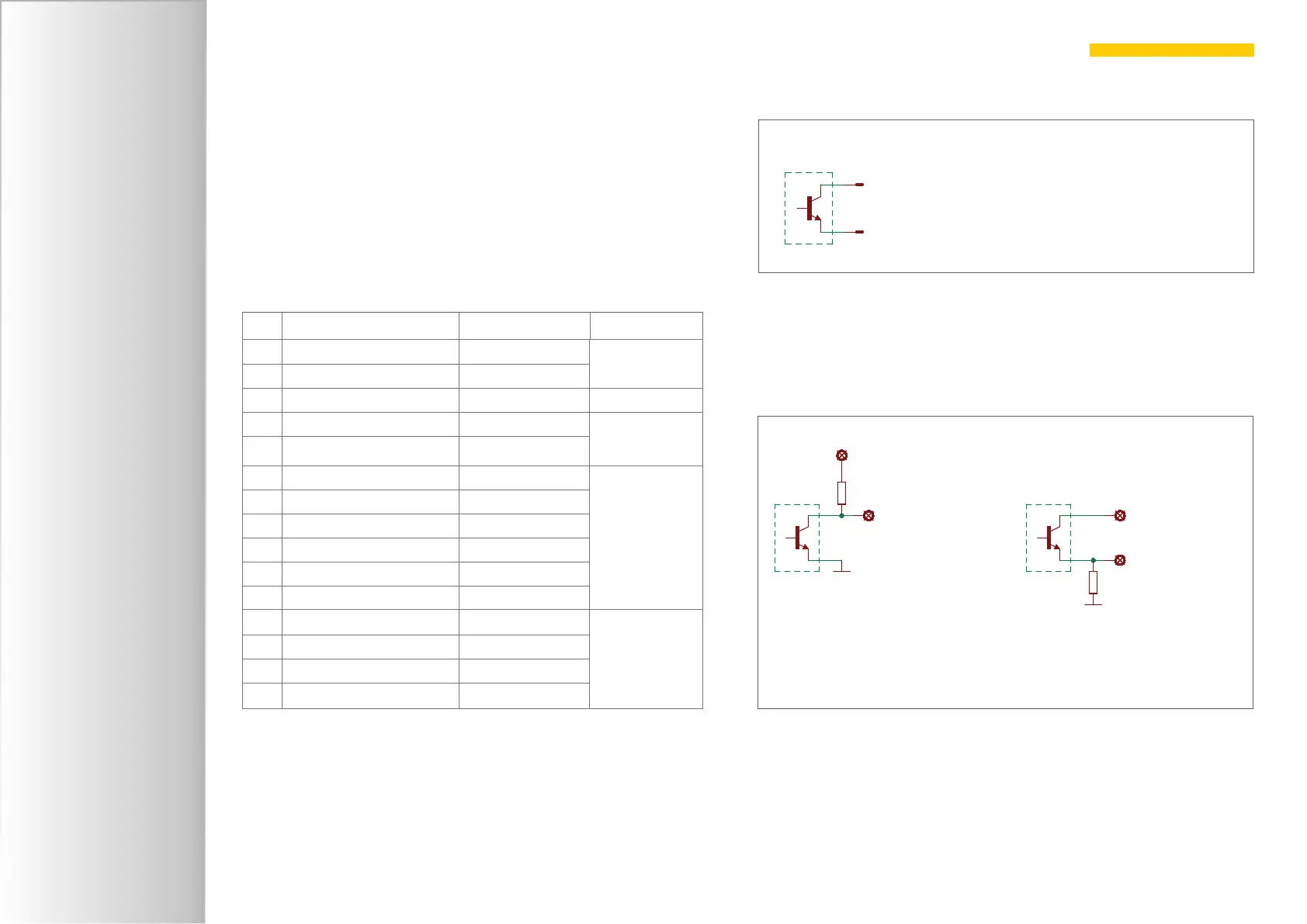
Collector (C)
E mitter (E )
Output Open Collector NPN
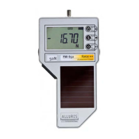
Connecting the digital outputs
R
+VDC
DIGOUT
GND
R
+VDCDIGOUT
GND
HIGH = closed
LOW = open
Connection examples
HIGH = closed
LOW = open