FMI-B
FMI-S
Bedienungsanleitung
Operation manual
Notice d’utilisation
Instrucciones de servcio
Istruzioni per l’uso
www.alluris.de
Page 7 of 34
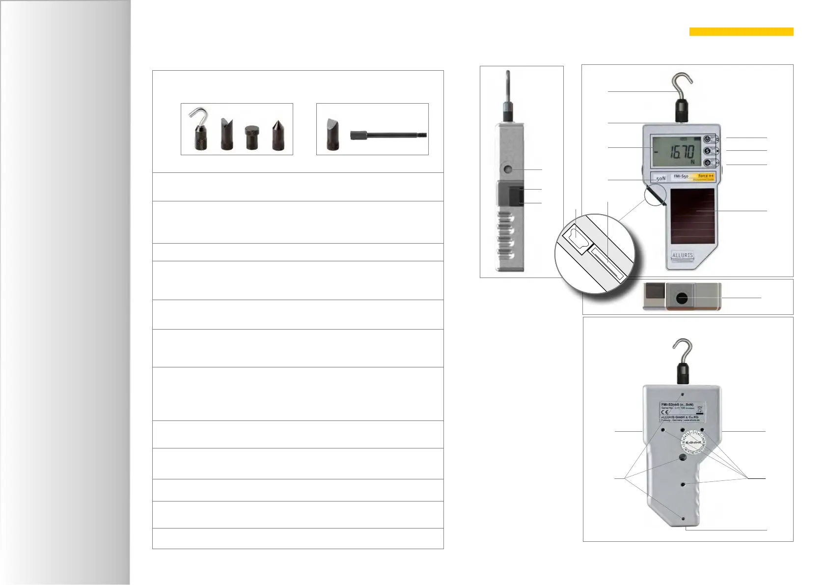
2.6. General remarks
1 Exchangeable attachments to apply force
(for more accessories see www.alluris.de)
2
Measuring axle for attachments to apply force
(M6, bzw. M10 (>1kN), L=13mm)
3
Display
Adapts automatically to changing positions with a 180° screen
rotation upon start (e. g. for test stand mounting)
4 Measuring range
5
USB 2.0 Mini-socket (series FMI-B30 und FMI-S30 and higher)
also for charging the LiPo-battery of FMI-B devices and fast
charging of FMI-S devices after long storage in the dark
6 10-pole Hirose socket (series FMI-B30 und FMI-S30 and higher)
for digital I/O’s, service, calibration etc.
7
I-key
On/Off (press 2 seconds); Start/Stop measurement;
select next item of menus
8
S-key
select operation mode; save data to the memory during the
measurement; show measuring results; select/deselect set-
ting menus (press 2 secs); select memory
9 O-key
Taring manually; select settings; select measurement units
10
Solar cell (FMI-S) for in- and outdoor use. Collects energy even
if the instrument is switched off.
11
Tapped holes (M10) to attach side handles or T-handle
12 Holes for location pins (8mm and 3mm without thread) for
allignment in test stands
13
Tapped holes (M4 and M5 ) for test stand mounting
7
8
3
4
9
2
10
1
5
6
11
5
6
11
12
13
11
11
11
Standard Special accessories