Disassembly
Among the different sizes of the A-Series - A 15 to A 50 - only the number of housing bolts [15] varies.
Besides, for the sizes A 08 and A 10 the shaft [16] additionally functions as the pilot piston for the air-valve. In
these pumps A 08 and A 10, there are no shaft piston rings [18] and no set screws [17] nor an air filter [20].
Please keep these differences in construction in mind when reading the following dismantling instructions.
The general design of the ALMATEC A-Series is simple. Two tools are delivered along with every pump. The
plastic one of these is designed for the mounting of the air-valve [22], the other one for the mounting of valve
seat [10]. Further special tools are not required.
• Before starting to disassemble the pump, take care that the pump has been emptied and
rinsed. Further the pump has to be cut off from any energy on the air and product side. If
the pump is being deported from the plant, a reference about the delivered liquid has to
be attached.
• Please respect the relevant additional security advices, if the pump has been used for
aggressive, dangerous or toxic liquids.
• Before putting the pump back into operation, the tightness of the pump has to be
checked.
Take the caps out of the side housings [1] to get access to the housing bolts [15]. Unscrew the housing bolts
[15] on one side using a socket wrench and remove the side housing [1]. Work carefully to ensure that the
sealing surfaces in contact to the diaphragms are not damaged. Carefully draw the housing bolts [15] out of
the pump. The center housing [2] and both side housings [1] are removeable now. Remove the sleeve [3] out
from the side housing [1]. Take the O-rings sleeve [11] out of the center housing [2] and both side housings [1]
for a possible renewal.
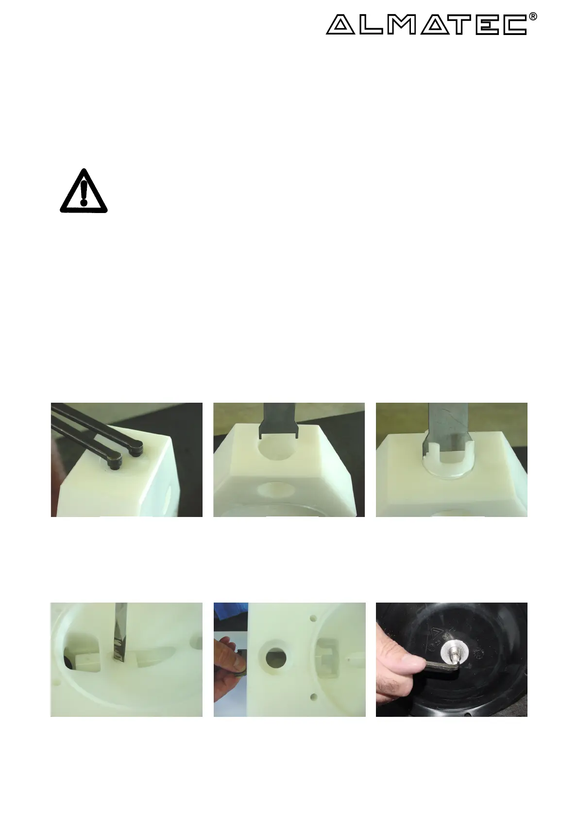
For further dismantling of the side housings [1], screw out the valve stop, discharge valve [6] with an
appropriate wrench (figure 6.1). Alternatively, you can stick two housing bolts [15] into the holes in the valve
stop [6] and loosen the valve stop with a third housing bolt [15] fixed in between the others. Take out the ball
valve [9] resp. cylinder valve [9] and the O-ring, valve stop, discharge valve [12]. Use the metallic mounting
tool to unscrew the valve seat [10] (figure 6.2/6.3).
figure 6.1 figure 6.2 figure 6.3
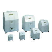
The plug, side housing [7] can be unscrewed the same way as described for the valve stop [6]. Loosen the
bolt, valve stop [5] with a screw-driver (figure 6.4). Push the valve stop, suction valve [4] towards the
discharge, so that the ball/cylinder valve [9] can be removed. Turn the mounting tool and screw the valve seat
[10] into the side housing [1] (figure 6.5). The valve seat [10] and the valve stop, discharge valve [4] can now
be removed from inside the side housing..
6
figure 6.5 figure 6.6 figure 6.4
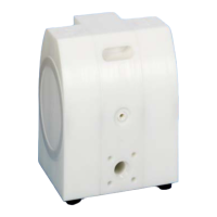
Screw one diaphragm [14] left-turning off the shaft [16] and pull the other diaphragm [14] out of the center
housing [2] using the shaft[16]. Take set screws shaft [17] out of the diaphragms [14] (figure 6.6). Remove both
parts of the shaft piston rings [18] from their grooves carefully (figure 7.1); do not damage the edges in the
center housing, a re-assembly of the same piston rings is impossible, they have to be replaced. Unscrew the