RC3-LOG & RC3P-LOG INSTRUCTION MANUAL Page 7
SHAWALMEX-EUROPE BV RC3-LOG & RC3P-LOG INSTRUCTION MANUAL SEPT 2018
4.4. Connection Assembly
Safety: Ensure the voltage, phase and cycle on the temperature control panel is the same as the power supply.
Turn the A/M switch to the 0 (off) position.
1. Install a suitable electrical connector to the power supply cable. Refer to the electrical specifications
indicated on the serial plate and in the record of purchase. Ensure the green wire is connected to earth.
2. Lift the covers on the platen connectors on the back panel of the temperature control panel and connect the
platen cables. Press the plugs firmly into the receptacles and rotate the latches to secure the plugs. When the
cables are removed, close the covers to protect the connector from water and dirt.
3. Connect the temperature control panel to the power supply. Refer to the electrical specifications indicated
on the serial plate and in the record of purchase. The temperature controllers should indicate the actual
platen temperature and the set point temperature.
5. OPERATION
The RC3(P)-LOG temperature control panel has one
datalogging temperature control unit, which controls
the temperature of the upper platen and the lower
platen. The average user need only adjust the
temperature set points for top and bottom platen. The
temperature controller has many other settings that
have been set by the factory.
The operator interface consists of a display screen and
four navigation push buttons.
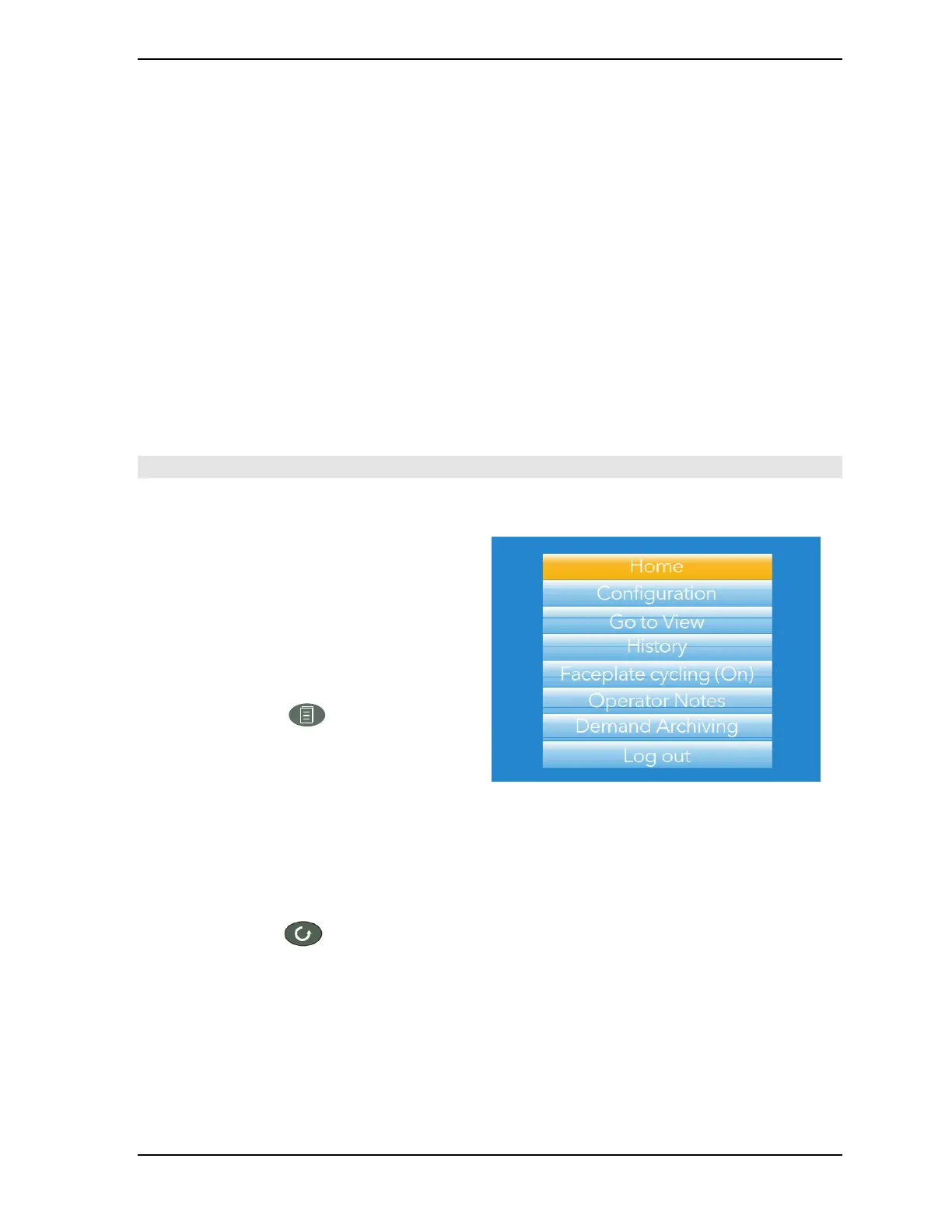
PAGE BUTTON
From any
non-configuration page,
pressing
this
push button causes
the top
level
menu
(figure 4:) to
ap
pear.
The
figure
shows
the
menu
for a user
logged
in with ‘Engineer’ level
access. Other access
levels
may
have fewer
menu items.
Within
configuration pages,
the Scroll
button
can
be used
as an
enter
key to
select
lower
menu
levels. In
such
cases
the
page button
is
used
to
reverse
this
action, moving
the user up
one
menu
level per
operation.
SCROLL BUTTON
From
trending pages, operation
of the scroll
push-button
scrolls
through
the
channels enabled
in the
group.
The
Faceplate
cycling
‘Off’
selection
can
be used
to
keep
a
particular channel
permanently displayed,
and
the scroll
pushbuttons
can
then be used
to
select channels
manually.
In
configuration pages,
the scroll key
operates
as an ‘enter’ key to
enter
the next
menu
level
associated with
the
highlighted
item.
Once
the
lowest menu
level is
reached, operation
of the
scroll key allows the value
of
the
selected
item to
be edited
by the
relevant means
(for
example,
the
raise/lower
keys, or a
keyboard entry).
The ‘Page’ key is
used
to
move
the user back up the
menu structure,
until the top level
menu
is
reached,
when
the scroll key can
be used again
to
return
to the
Home
page.