17
We reserve the right to modify technical specifications without prior notice.
83051400aUK © Alpha-InnoTec GmbH
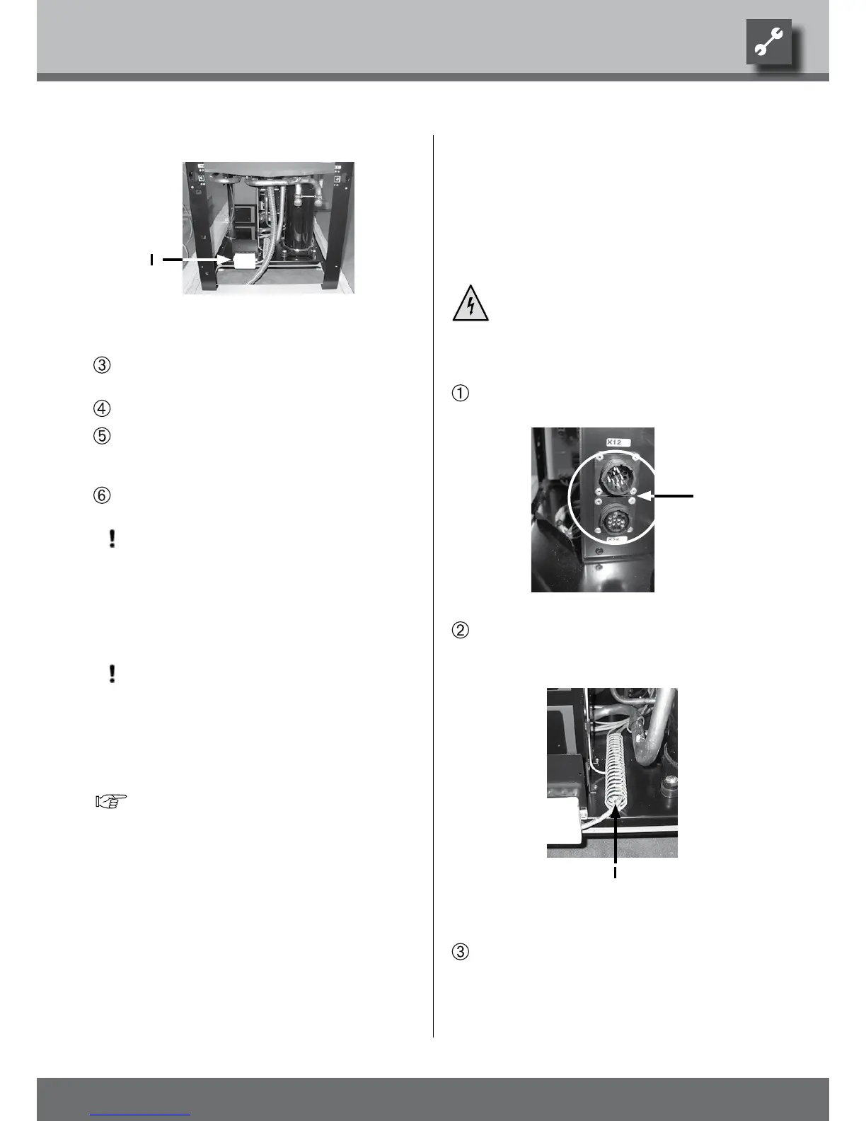
lw140a/rX:
1 Connection box for compressor
Connect power cable to the connection box (elec-
tric heating element on-site)...
Close connection box...
Install power cable in a conduit as far as where it
enters the building and from there on to the fuse
box...
Connect power cable to power supply.
ATTENTION
Ensure clockwise rotary eld of the load power
supply (compressor).
– An incorrect rotary eld of the compressor
during operation can cause serious, irreparable
damage to the compressor.
ATTENTION
Make sure to equip the power supply of the heat
pump with a 3-pole automatic cut-out with at
least 3mm contact gap.
Note the level of the release current.
Overview “Technical data / scope of delivery”,
“Electric” section.
heatpumpsideConneCtionoFtheControland
sensorwires
The heat pump is connected to the heating and heat
pump regulator by means of the control and sensor
wires. They are connected at the electric switch cabi-
net on the switch cabinet side (= operator side) of the
heat pump.
DANGER!
Danger of fatal injury due to electric
shock!
Unit must be disconnected from the pow-
er supply.
Screw control and sensor wires to the two connec-
tors on the side of the electric switch cabinet...
Guide control and sensor wires inside the unit
through the provided cable duct to the water con-
nection side...
1 Cable duct for control and sensor
wires (only LW 140A/RX)
Guide control and sensor wires out of the unit...