36
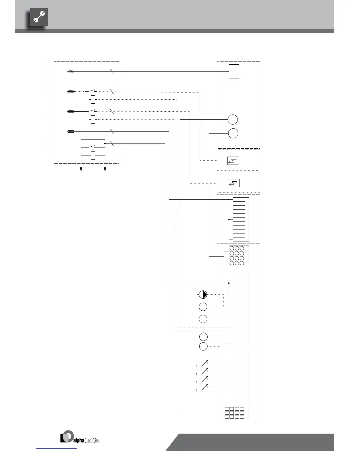
-F10
-F13
A1
A2
-K13
-F14
A1
A2
-K14
-F11
A1
A2
M
ZIP
M
ZUP
ZIP
ZW2
M
X52
-X8
Plug on switch box heat pump (gauge line)
N
3-pol. Cut out compressor; Attention: Right-hand ro t. eld is mandatory!
5
ZW2/SST
A6
ZW1
ZW1K13
10
-X5
4
X1/X5
F10
Cut out controller unit
5
Contactor electric heating element buer tank
5
F11
Heat pump
L1
A1
5
3~N/PE/400V/50Hz
PE
TB1
HUP
BUP
TA
11
-X12
A2
UK831164
HUP
X8
PE
-X1
MZ1
N
PE
ZW2/SST
ZW2
4
Sub-distribution unit internal installation
RFV
Distribution box in heat pump; power supply output compressor
MIS
7
Ventilator; internally wired
A1
Terminal strip in switch box wall regulator; N/PE d istribution for external 230V devices
Control signal of additional heat generator 2
L
M
-X0
2
N
A3
VBO
ZUP
-X3
Auxiliary circulation pump
-X2
Air water outside
X7
TBW
1
MA1
EVU
HUP
3
Terminals in switch box wall regulator
7
A4
GND
2
Plugs on controller board (see sticker)
9
3~PE/400V/50Hz
FP1
BUP
N
Terminals
ZW1
Name
MOT
12
TBW
8
3
PE
6
Terminal strips on controller board (see sticker)
A2
Hot water or buer stor
age tank
GND
A4
X0-X4
VBO
ZUP
Control signal of additional heat generator 1
External return sensor
8
Charge/discharge/cooling mixer 1 open
3
Pump for mixing circuit 1
External sensor
1
Hot water circulating pump/switching valveBUP
A3
Plug on switch box heat pump (control line)
Contactor electric heating element hot water or buf fer tank
A6
11
ZW2
X12
ZIP circulation pump
I
nf
or
m
ati
on
on
fus
e
s
c
an
be
foun
d i
n
the
tec
h
ni
c
al
d
ata
-X52
F14
-X7
Cut out auxiliary heating 2
ZW1
K14
A5
A5
3~N/PE/400V/50Hz
RFV
Hot water or buer storage tank
Cut out auxiliary heating 1F13
L1
No function
TB1
L1
ZW1
-X4
RFV
Energy supplier contact; closed on release; bridge if no blocking interval
FP1
N
MOT
2
TB1
1~N/PE/230V/50Hz
EVU
GND
Overload protection; internally wired
TRL
Function
B10 A
9
MA1/MIS
TA
GND
Controller board; Attention: I-max = 6A/230VAC
PEX
TA
Legend:
ASD
TBW
TRL
Charge/discharge/cooling mixer 1 closed
PE
GND
GND
104
12
PEX
6
Sensor mixing circuit 1
Hot water gauge/thermostat
EVU
Heating circuit circulating pump
MZ1/MIS
Accessories: Remote control