39
L Reg
/1.13
MOT
/1.13
R23
/1.13
N Reg
/1.13
PE
/1.13
12
-X12
L
-X7
6
1
11
N
P
+-
b2 c4
a1
-F1
HDP
5
12
/1.6
34
/1.6
56
/1.6
21 22
/1.6
1
A1
A2
-K1
VD1
10
-X12
A1
A2
-K3
7
-X12
2
-X7
-Y1
3
-X12
P
+-
c4
a1
-F2
NDP
P
-+
c4
a1
-E1
AEP
9
-X12
ϑ
1
-X52
-R4
TRL
2
ϑ
3
-R5
TVL
4
ϑ
5
-R6
THG
6 7 8 9
29
-X7
-R10
CW
10
30
ϑ
11
-R7
TWEFS
12
12
/1.9
34
/1.9
56
/1.10
21 22
/1.11
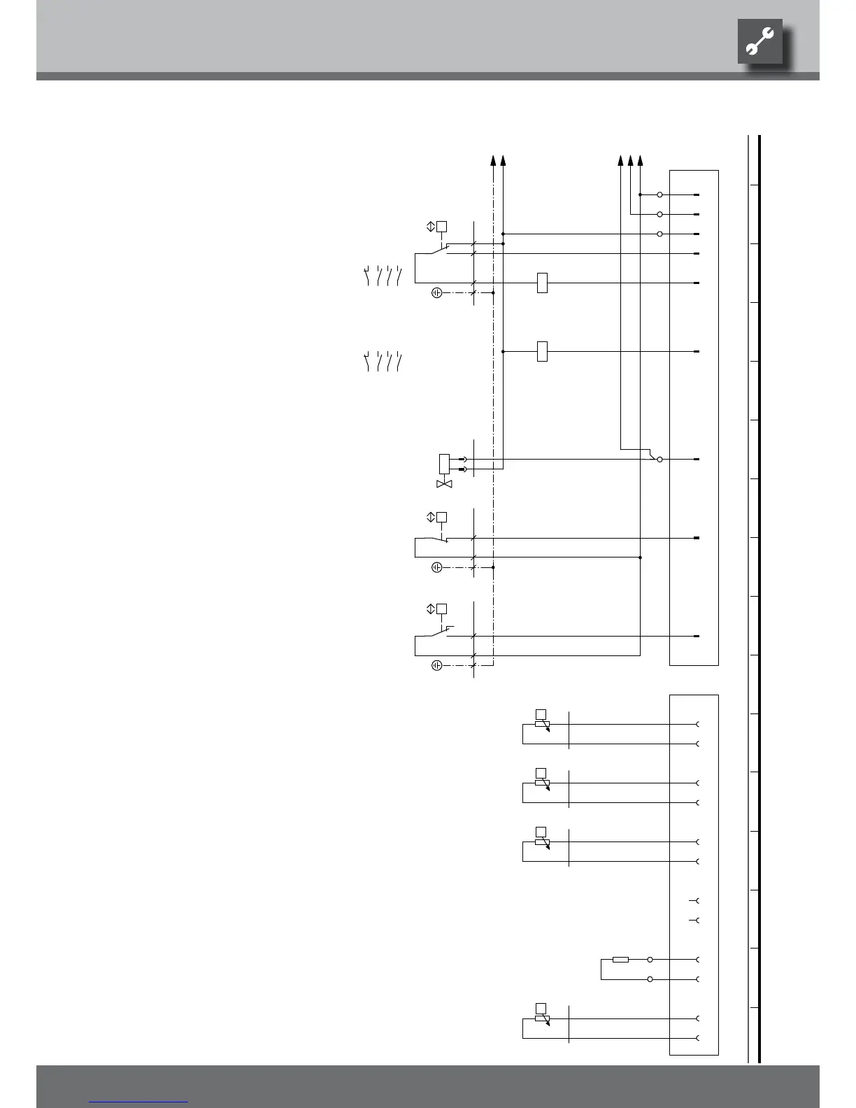
Y1
Safety temperature limiter heating element
ZW1
STB
-Y1
K6
L1
Contactor for auxiliary heating
Flow sensor
TRL
Low-pressure switch
-X52
TWEFS
ASD
Defrosting valve
Legend:
NDP
E1 Defrosting pressostat
VD1MOT
X7
R3
Terminal in switch box heat pump
X12
Function
AEP
Contactor for compressor 1
HDP
R10
-X12
F2
HD
Operating materials
VBO
VD1
UK817072
Plug on switch box heat pump (control line)
Contactor fanK3
bl
Hot gas sensor
-F1
N
TWA
Encoding resistor, 2700 Ohm
bl
bl
2PE
Freeze protection sensor
THG
R7 TWEFS
1
AV
-E1
ND
VBO
rt
TVL
THG
TRL
Plug on switch box heat pump (gauge line)
R5
F1 High-pressure switch
K1
PE
R4
X52
Return sensor
CW
If installed: heat source outlet gauge
bl
PE
TVL
R6
-F2
We reserve the right to modify technical specifications without prior notice.
83051400aUK © Alpha-InnoTec GmbH
Circuit diagram 2/2 LW 90A/RX • LW 140A/RX