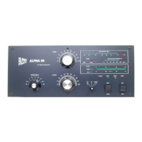
5.0 CONTROL & INDICATOR FUNCTIONS (See fig. 6, page 10)
5.1 RF OUTPUT, GRID CURRENT, and REFLECTED POWER bargraphs are peak-reading and generally
self-explanatory. Example: 1.5 kW output (forward power into a 50 ohm load) is indicated when all green
LED segments to the left of the 1.5 (kW) label are fully lighted and the first red LED segment is dark. The
primary calibration point for RF OUTPUT is at 1.5 kW on 14 MHz.
5.2 TUNF/IP/HV/DRIVF./LOAD VSWR "multimeter": The function of this indicator is selected by buttons at
its right. It is a moving-dot display. HV (plate voltage) is read on the 0-3 kV top scale. Ip (average plate
current) is displayed on the 0-1.5 A next lower scale. INPUT DRIVE is read on the same scale as Ip, with full
scale 150 watts. VSWR (3:1 maximum) is read on the bottom scale. The TUNE meter function permits fast
and safe manual tuneup at reduced power.
5.3 BAND switch: Each band switch position selects the amateur band indicated in MHz.
5.4 TUNE control: Varies plate tuning capacitor to set output circuit to resonance.
5.5 LOAD control: Varies plate loading capacitor to establish optimum amplifier power output level.
5.6 CW/SSB rocker switch: Selects optimum operating bias for emission type. CW provides highest efficiency
for non-linear modes including CW and FM, and SSB provides best linearity for SSB, AM, and SSTV (also
okay for CW and FM).
5.7 OPR/STBY rocker switch: Selects operate or standby modes.
5.8 ON and OFF rocker switches: momentary action switches turn the ALPHA 89's main AC power on or off.
5.9 Special rear-panel connections:
a) ALC & ALC Adjust - See section 8.3.
b) RELAY - Switches amplifier from receive to transmit when connector center pin is shorted to ground.
c) KEY OUT - Provides a contact closure which follows the keying line connected to the RELAY jack
whether the amplifier is in ON, STANDBY, or OPERATE condition. Useful for special T/R hook-ups when
amplifier is used with exciters having poor T/R sequencing. Contact ETO customer service for specific
advice.