30
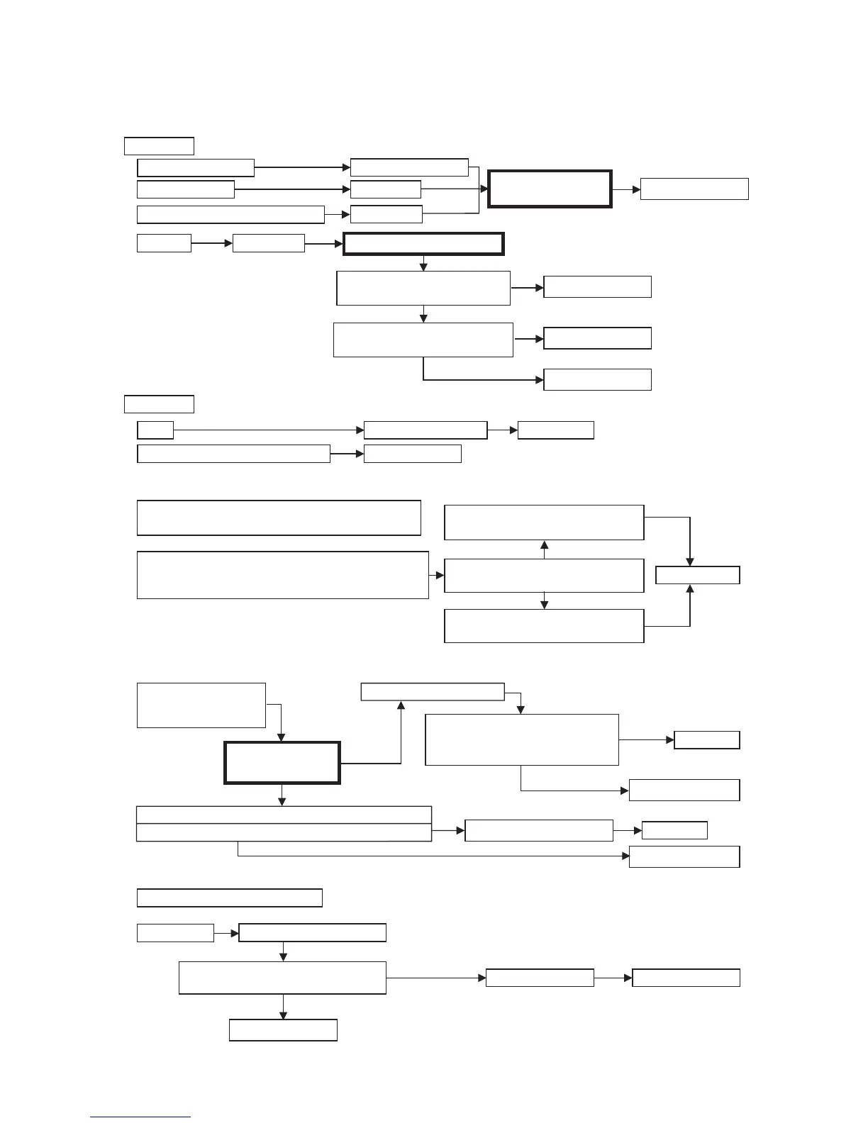
Alpha CD13R, 18R, 24R - Fault Finding
10.2 FAULT FINDING SOLUTIONS A to E
NO
YES
Pump
If pump jammed, release
Replace PCB
NO
PCB - X6 connector, terminals 18, 19
B
Replace pump
1.
2.
240 V ac at:-
Replace PCB
Replace PCB
Replace PCB
Replace transformer
NO
NO
NO
NO
YES
NO
NO
NO
Main terminals L and N
Check electrical supply
Replace fuse
Check wiring
Main terminal fuse
PCB - X1 connector, terminals 55, N
Neon D
illuminated continuously
A
240 V ac at:-
1.
2.
3.
NO
YES
Replace fuse
Neon D illuminated contiuously
Is 240 V ac across
PCB X4 connector terminals 11,12
Is 26 V ac across
PCB X11 connector terminals 40,41
PCB fuse
4.
PCB - X7 connector,
is 240 V across terminals 26, 27
YES NO
E
Gas at burner
Replace gas valve
Adjust gas valve
NO
NO
Ensure gas is on and purged
Check pressure tubes are connected
Replace PCB
C
Primary temp. sensor faulty. Cold resistance approx.
12-14 k ohms (resistance reduces with increase in temp.
i.e. when hot, resistance is approximately 3 k ohms)
Check and correct connections/wiring at
temperature sensors and PCB
2.
1.
YES
YES
Check resistance throughout
the range from cold to hot
Primary return temperature sensor faulty
i.e. no heating
Primary flow temperature sensor faulty
i.e. no heating
Replace sensor
D
Check and correct:-
1. Electrical connections
2. Restriction in flue
Neon A and B flashing
at the same time
YES
YES
(BUT)
1.
Replace PCB
Replace PCB
YES
NO
NO
2.
3.
Fan connections correct at fan and PCB connector X12
Fan runs at maximum speed
PCB connector, is 36 V dc across terminals 39 and 37 or 38
Fan jammed or faulty winding
Is dc volts at PCB, X12 connector:-
across terminals 35 and 37-3to9Vdc
across terminals 36 and 37-3to9Vdc
YES
YES
YES
Replace fan
Replace fan