28
8.12 VIEWING WINDOW - Refer to Fig. 27
1. Gain access behind the casing as in Section 8.1.
2. Remove the rubber window frame and remove the damaged glass.
3. Re-assemble in reverse order with a new glass. Ensure the rubber frame is located correctly in the front panel.
8.13 TERMINAL BLOCK FUSE - Refer to Fig. 22
The fuse is located in the boiler terminal block.
1. Gain access as described in Installation, Section 4.8.
2. Lift out the fuse holder and remove the fuse. Fit a fast blow 2 A fuse as a replacement, ensuring that the holder snaps into position.
3. Re-assemble in reverse order, ensuring the terminal block is located correctly on the plastic pins.
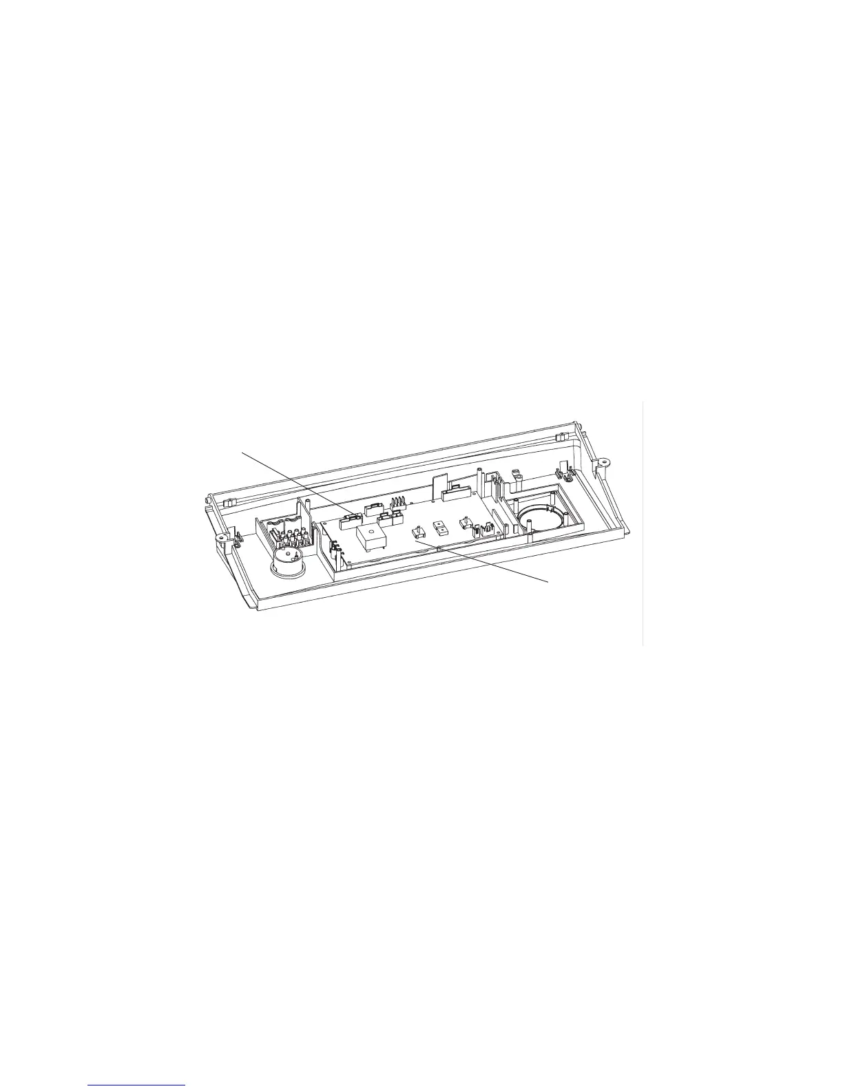
8.14 PCB - Fig. 31
1. Gain access behind the control panel as described in Section 8.1.
2. Disconnect all the wiring connectors from the PCB.
3. Remove the five fixing screws and carefully withdraw the board from the switch spindles.
4. Re-assemble in reverse order. Refer to the wiring diagram in Section 9.1 for connections.
5. Light the boiler and adjust the PCB as described in the instructions supplied with the replacement PCB.
Alpha CD50 - Component Replacement
Fig. 31
8.16 CLOCK (if fitted) - Refer to Fig. 23
Note: For replacement only use an Alpha single channel clock. Do not fit a two channel clock.
1. Gain access behind the control panel as described in Section 8.1.
2. Remove the two screws securing the clock cover at the rear of the control panel.
3. Disconnect the wiring from the clock.
4. Remove the clock retaining screws and withdraw the clock from the control panel.
5. Fit the new clock, and connect the wires as follows:-
Blue to terminal 1, Brown to terminal 2 and Red wires to terminals 3 and 4, (or as per the instructions supplied with the clock).
6. Re-assemble in reverse order. Refer to the User's instructions and the boiler's control cover to set the clock.
8.17 DIVERTER VALVE MOTOR - Refer to Fig. 33
1. Gain access as described in Section 8.1.
2. Remove the two screws securing the motor assembly to the valve body and remove the motor assembly. These screws are
accessible from underneath the boiler.
3. Remove the two screws securing the motor cover and remove cover.
4. Disconnect the motor's wiring from the terminal block (noting their positions) and remove the motor.
5. Re-assemble in reverse order.
Connect the wiring as follows:- Black wire to terminal N, Red wire to terminal R and Orange wire to terminal A.
PCB fuse
PCB