29
Alpha CD50 - Component Replacement
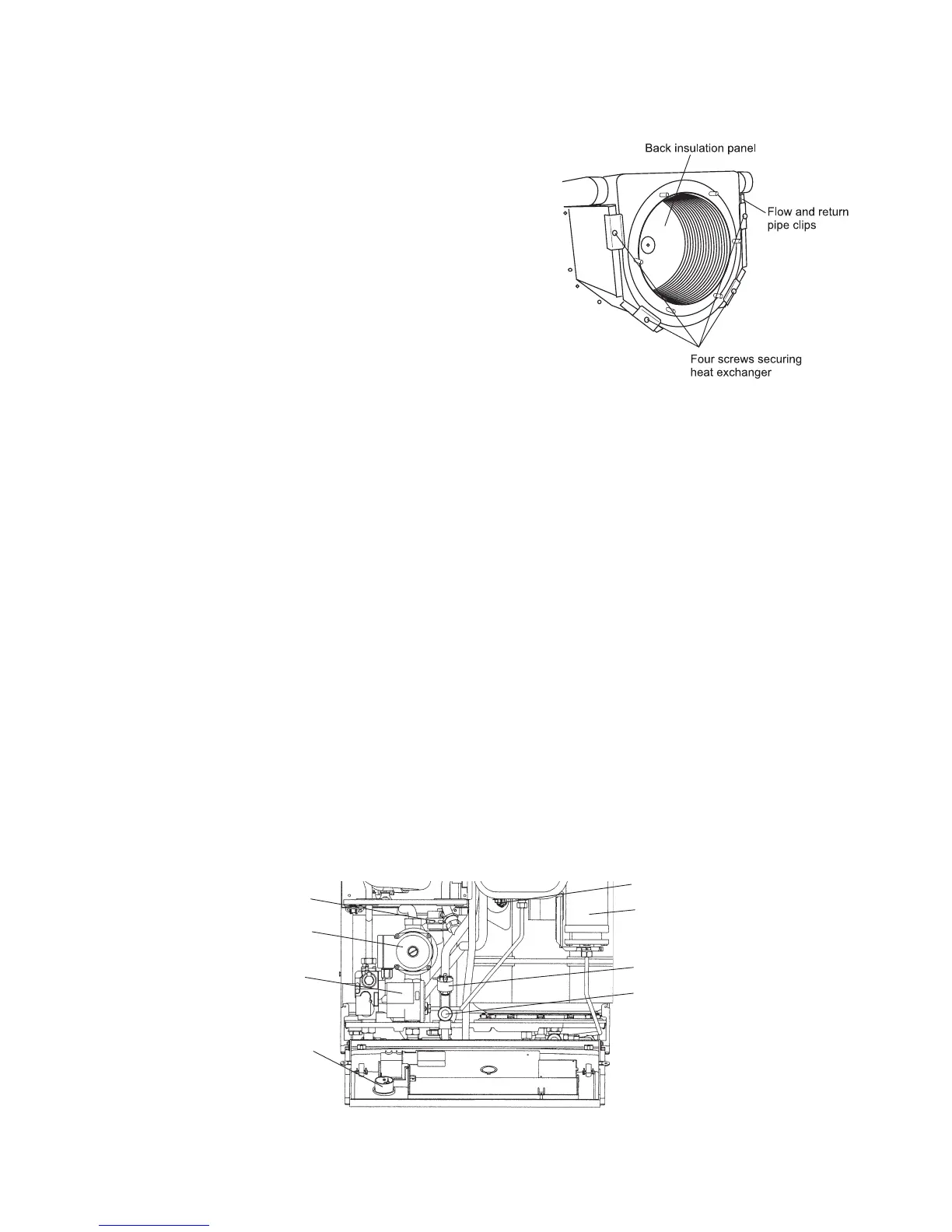
8.18 PRIMARY HEAT EXCHANGER - Fig. 32
1. Gain access behind the room sealed chamber panel as described
in Section 8.1 and drain the boiler heating circuit as described in
Sections 8.1 and 8.2.
2. Disconnect the gas inlet union from the combustion chamber front.
3. Remove the two screws and six nuts and washers securing the
combustion chamber front burner assembly and remove.
4. Remove the overheat thermostat (Section 8.9), flue thermostat
(Section 8.10) and the primary temperature sensor (Section 8.20).
5. Disconnect the condensate drain union.
6. Remove the two clips from the heat exchanger flow and return
pipes and disconnect the unions at the pump and diverter valve.
7. Remove the four screws securing the heat exchanger retaining
brackets.
8. Lift up the heat exchanger off the pipes and remove it by carefully
withdrawing it out of the boiler.
9. Re-assemble in reverse order, ensuring that new seals are used.
Lubricating the seals with the grease supplied will aid assembly.
10. Refill and pressurise the system. (Refer to Commissioning, Section 5.1).
8.19 COMBUSTION CHAMBER INSULATION
Gain access to the combustion chamber as described in Section 8.1.
Front insulation - refer to Fig. 28
1. Remove the electrodes from the combustion chamber front as described in Section 8.3.
2. Remove the four screws securing the burner.
3. Carefully remove the insulation.
Back insulation - refer to Fig. 32
1. Remove the combustion chamber front/burner assembly.
2. Remove the centre screw retaining the insulation.
3. Carefully remove the insulation, suction applied to the centre of the insulation will aid this.
Fit a new panel and re-assemble in reverse order.
8.20 PRESSURE GAUGE - Fig. 33
1. Gain access as described in Section 8.1.
2. Drain the boiler heating circuit as described in Section 8.2.
3. Remove the nut securing the pressure gauge sensor to the return manifold and withdraw the sensor.
4. Remove the gauge from the control panel by depressing the plastic lugs on the gauge.
5. Fit the new gauge using a new washer to seal the sensor connection.
6. Refill and pressurise the system. (Refer to Commissioning, Section 5.1).
Fig. 33
Fig. 32
Primary pressure switch
Automatic air vent
Pump
Pressure relief valve
Pressure gauge
Pressure gauge
sensor behind
diverter valve
Store temperature sensor
DHW expansion vessel