30
8.21 TEMPERATURE SENSORS - Refer to Figs. 29 and 33
The temperature sensors fitted to the hot water storage (dry pocket) and primary heat exchanger (wet pocket) are both the
same.
1. Gain access as described in Section 8.1. When replacing the primary sensor, drain the boiler as described in Section 8.2.
2. Disconnect the wiring and unscrew the sensor. Re-assemble in reverse order with a new sensor.
8.22 AUTOMATIC AIR VENT - Refer to Fig. 33
1. Drain the boiler heating circuit as described in Section 8.2.
2. Unscrew the automatic air vent from the pump outlet. Fit a new one using a new 'O' ring.
3. Re-assemble in reverse order.
4. Refill and pressurise the system. (Refer to Commissioning, Section 5.1).
8.23 PUMP - Refer to Fig. 33
Drain the boiler heating circuit as described in Section 8.2.
Pump Head
1. Remove the four socket head screws securing the pump head to the body. Withdraw the head, remove the wiring cover
and disconnect the wiring.
2. Connect the wiring to the new head as follows:-
Brown to L, Blue to N, Green/yellow to .
Ensure the pump is set to maximum (3) and re-assemble in reverse order.
3. Refill and pressurise the system. (Refer to Commissioning, Section 5.1).
Complete pump
1. Disconnect the pump unions and withdraw the pump, remove the wiring cover and disconnect the wiring.
2. Unscrew the automatic air vent from the pump outlet.
3. Connect the wiring as described above, ensure that pump is set to maximum and re-assemble using new sealing washers.
4. Refill and pressurise the system. (Refer to Commissioning, Section 5.1).
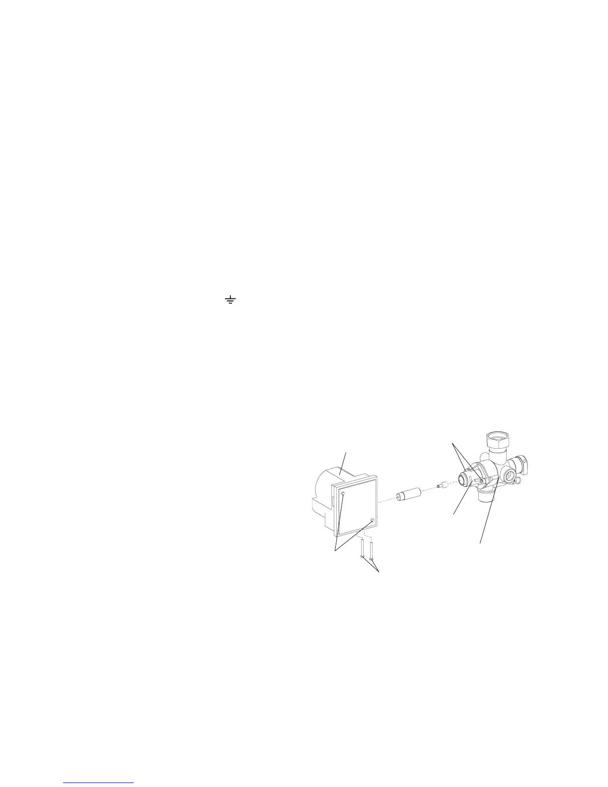
8.24 DIVERTER VALVE ASSEMBLY - Refer to Figs. 33 and 34
1. Drain the boiler heating circuit as described in Section 8.2.
2. Remove the diverter valve motor as described in Section
8.17.
3. Remove the two 4 mm allen screws and pull the plastic
housing from the manifold.
4. Fit the new valve assembly in reverse order using new
seals.
5. Refill and pressurise the system. (Refer to Commissioning,
Section 5.1).
8.25 HEATING PRESSURE RELIEF VALVE
Refer to Fig. 2
1. Drain the boiler heating circuit as described in Section 8.2.
2. Disconnect the relief valve outlet fitting. Undo the screw
securing the relief valve and pull out the valve.
3. Re-assemble in reverse order using a new 'O' ring seal.
4. Refill and pressurise the system. (Refer to Commissioning,
Section 5.1).
Alpha CD50 - Component Replacement
Fig. 34
Diverter valve
manifold
4 mm Allen screws
Diverter valve motor
Cover
screws
Diverter valve
housing
Motor securing
screws