10
C048-699-30 R03, Rev. B (01/2021)
Step 3. Once the DCX unit is in it's nal position, mark the DCX
mounting bracket hole locations onto the battery stack frame top
rails (see Figure 10).
Step 4. Uninstall the termination plate from the battery terminals, then
uninstall the DCX mounting brackets from the DCX unit.
Step 5. Align the DCX mounting brackets with the marked locations from
Step 3 and secure into place by tightening the included self-
tapping screws (EnerSys/C&D/GNB battery kits, Figure 11) or by
tightening the included 1/4 in. hardware into the threaded inserts
of the mounting brackets (East Penn Manufacturing kits).
Step 6. Reinstall the DCX unit into position again as described in Step 2,
then tighten all hardware. See Table 4 for DCX mounting
bracket to DCX chassis torque specications.
NOTE: REFER TO BATTERY MANUFACTURER TORQUE
SPECIFICATIONS FOR TIGHTENING BATTERY
TERMINATION PLATE TO BATTERY TERMINAL POSTS
(FIGURE 12).
NOTICE:
Table 4. Mounting Bracket to DCX Chassis Torque Specications
TERMINATION
TYPE
HOLE/STUD
SIZE
RECOMMENDED
TORQUE VALUE
Threaded Insert 3/8 in. 50 in·lbs
Step 7. After mechanical mounting of DCX unit has been completed,
snap the two black plastic hole plugs into the access holes that
cover the 3/8 in. mounting bolts (see Figure 13)
4.4 4.4 Chassis GroundChassis Ground
DO NOT ENERGIZE THE DCX BATTERY
DISCONNECT SWITCH BEFORE CHASSIS GROUND
IS CONNECTED.
CAUTION!
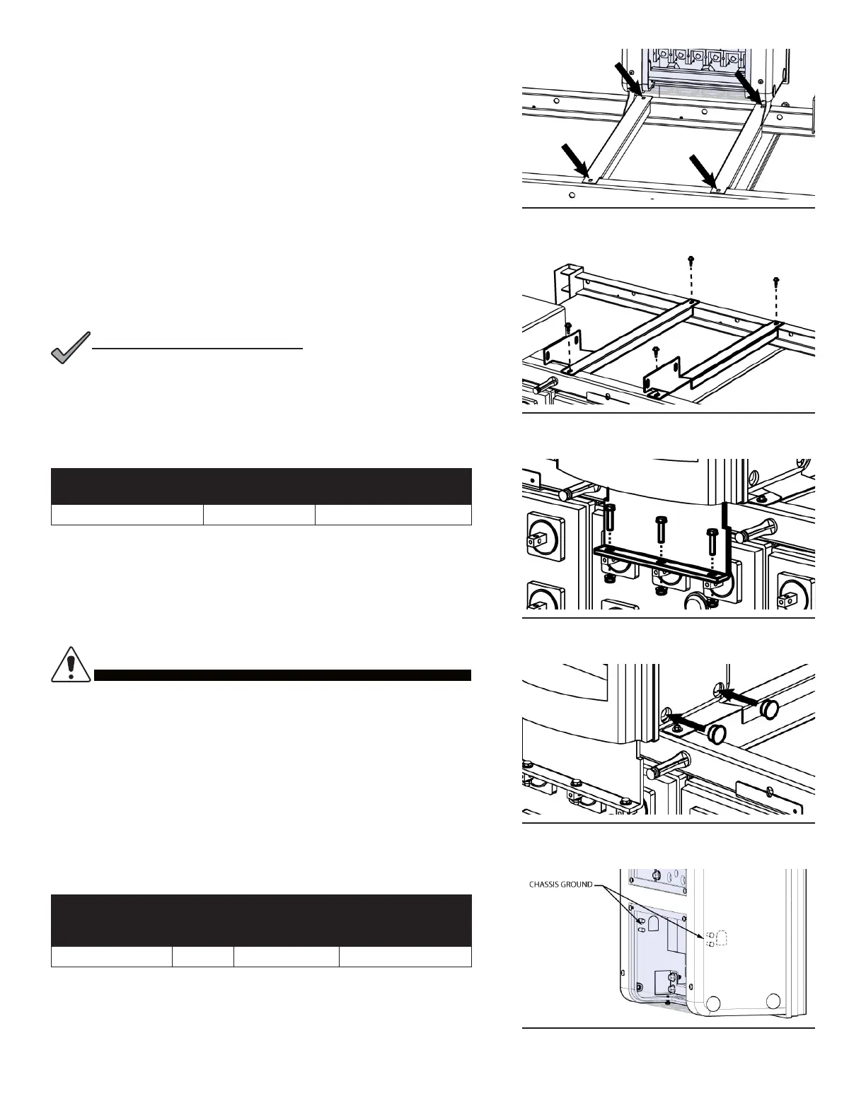
Two chassis ground landings are located on the inside of the DCX
chassis (see Figure 14). Refer to mechanical drawing found in
Appendix A.3 for greater detail regarding grounding locations. A
minimum of #6 AWG chassis ground cable is required. IMPORTANT:
Grounding hardware not included. A properly-sized grounding
conductor must be installed per NEC (250.122).
Table 5. Chassis Ground Specications
TERMINATION
TYPE
HOLE/
STUD
SIZE
CENTER TO
CENTER
RECOMMENDED
TORQUE VALUE
Threaded Stud 1/4 in. 5/8 in. 5.83 ft·lbs
Step 1. Select the desired grounding location and break away the
associated knock-out points found on the clear plastic covers.
Step 2. Connect the ground cable with 1/4 in. hardware. Ensure heat
shrink and no-oxide compound are applied appropriately prior to
termination. Torque the fasteners to 5.83 ft·lbs (see Table 5).
Figure 10. Mark bracket locations
Figure 11. Secure brackets
Figure 12. Secure to cell terminals
Figure 13. Insert hole plugs
Figure 14. Chassis ground