11
C048-699-30 R03, Rev. B (01/2021)
4.5 4.5 Battery Positive ConnectionBattery Positive Connection
The DCX unit requires battery positive to be connected via a small
gauge wire from the battery positive terminal post of the battery string
to the battery positive terminal block input on the circuit board located
behind the ip-up front panel of the DCX unit.
Step 1. Install a #14 to #16 gauge wire in the “VIN RETURN” terminal
position. Connect the other end of this wire to the +48V battery
positive connection on the battery string. Route the wire securely
away from potential chafe points with metal connections. The
DCX unit is shipped with a wire that includes an in-line KLM
fuseholder. See Figure 15 for alarm connections.
4.6 4.6 EPO Emergency Power O Switch OptionEPO Emergency Power O Switch Option
The DCX unit is equipped with a terminal block input connection for a
remote emergency power o “EPO” switch. External dry contact switch
closure is required.
DO NOT WIRE IN COMMON WITH ANY OTHER
ELECTRICAL DEVICE OR APPLY A VOLTAGE ON THIS
INPUT FROM ANY OTHER SOURCE OR DAMAGE WILL
OCCUR. ONLY CONNECT A DEDICATED EXTERNAL DRY
CONTACT CLOSURE NORMALLY OPEN SWITCH TO THIS
CIRCUIT.
CAUTION!
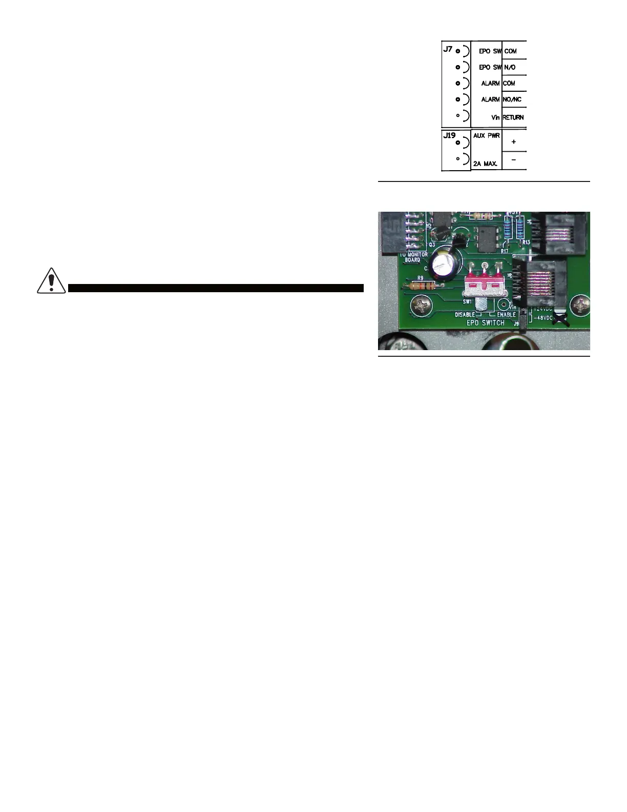
Figure 15. Connections
Figure 16. EPO Switch
An external wall mount mushroom head switch is commonly used for EPO functions. Route the two conductors from the
switch to the DCX terminal block positions labeled “EPO SW COM” and “EPO SW N/O”. The DCX unit is shipped with
the EPO switch function disabled via a slide switch located on the circuit board (see Figure 16). Slide this switch to the
“enabled” position if the EPO function is desired.
4.7 4.7 Alarm ContactsAlarm Contacts
The DCX unit comes with an alarm relay with contacts routed to the terminal block on the circuit board assembly. The
alarm contacts are rated 0.5A. Remote alarm sensing can be connected to the alarm contacts to provide an alarm when
the DCX circuit breaker is o-line or there is an alarm condition. NOTE: The DMP digital monitor panel option also uses
these alarm contacts to convey other alarm conditions such as over-temperature and other alarm options. Route the
alarm wires securely via the cable tie anchor provided below the circuit board assembly.
4.8 4.8 Auxiliary Power PortAuxiliary Power Port
Auxiliary power is available on the terminal block labeled “AUX PWR.” for powering small 48V nominal loads. This power
is diode-ORed from the battery and line and will carry whichever voltage is higher. It is unregulated and protected by the
DCX input GMT fuses. 2A is the maximum load supported.
4.9 4.9 Electrical TestElectrical Test
Prior to output cable installation, follow these steps:
Step 1. Flip the DCX breaker to the OFF position. Ensure that the battery positive wire is installed and routed securely.
Ensure that the EPO switch and alarm contact wires are installed if used and routed securely.
Step 2. Ensure that the remote EPO switch is in the o position (if used). Connect the battery string cell connection bus
bars that were left disconnected for safety purposes during the DCX unit installation. Upon connection of the series
string, the “OFF-line” LED will light up.