31
Alpha InTec² 26E, 30CE and 35CE - Commissioning
When the settings have been correctly adjusted at the three output levels press the 'Summer/Winter' (
) button to save
and exit the calibration setup menu.
Fast calibration
Fast calibration is a self-adjusting process carried out by the boiler if the following are relevant;
1. A new gas valve fitted.
2. A new fan fitted.
3. Long flue length (accompanied by f0 parameter adjustment).
4. Other service or repair work is carried out.
To access the fast calibration mode, turn the DHW selector to 6 o'clock and the CH selector to 9 o'clock (see Fig. 5.4).
Press the 'RESET' button for eight seconds until the parasol and snowman (
) flash at the same time (chimney sweep
mode), then press the 'INFO' button within three seconds. Once the function is active, the boiler sequentially carries out the
procedure require to calibrate the appliance to the maximum, medium and minimum heat output values.
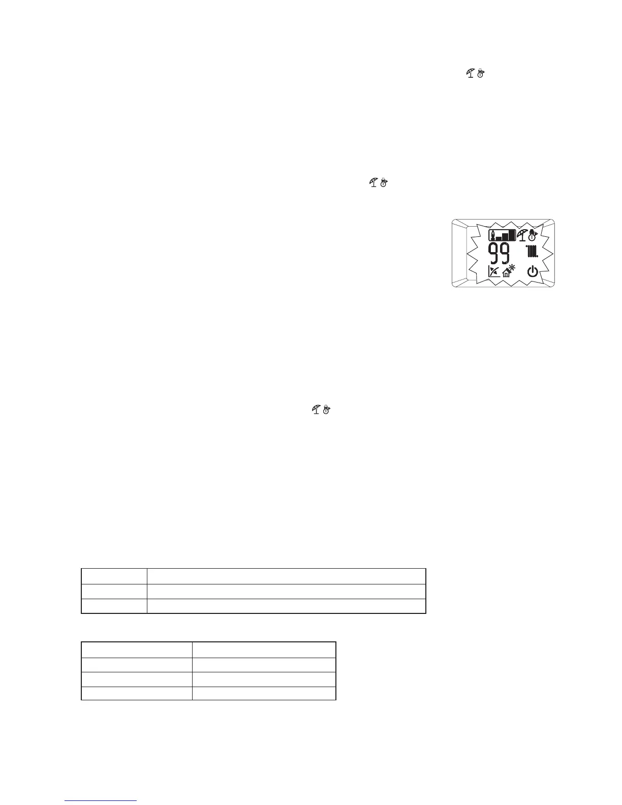
At this stage the display icons flash, 'summer', 'winter', 'stand-by', 'external sensor', 'solar
sensor' and the operating temperature is displayed, alternating with the current operating heat
output. See Fig. 5.6.
The boiler will now operate for approximately five minutes at different output settings
(max. med. min) automatically adjusting the gas valve to give the correct CO
2 settings. No
intervention is required and the boiler will exit this function automatically when completed. If
the flow temperatures are getting up to maximum operating temperature during the procedure
it is possible to open a hot tap to lose the heat (combination boilers only).
Caution: In this mode the only active temperature control is the flow sensor that limits the
maximum temperature leaving the boiler to 90 °C, therefore be careful when running a hot tap.
5.14 PROGRAMMING THE PCB
The PCB defines the output and operating mode and the boiler. The correct operation and output of the appliance is defined
according to the setting of parameters in menus 'n' and 'F'.
For this reason it is recommended not to alter the parameters of these menus in order not to compromise the correct
operation of the boiler.
To activate the parameter menus the DHW selector must be set to 6 o’clock and the CH selector set to 9 o’clock positions
(see Fig. 5.4), then press the 'RESET' and 'Summer/Winter' (
) buttons simultaneously for 8 seconds. the screen will now
display the parameter group and parameter number followed by the parameter value.
Once the programming mode has been accessed, scroll through the five groups (G, P, t, A, F) by pressing the 'Summer/
Winter' button for 1 second.
Menu G is for the air-gas control settings with two sub-menus (n and S), relating to fan and gas valve control settings. Every
time these parameters are altered, the full calibration procedure must be carried out. In order to access sub-menus 'n' and 'S'
press the 'RESET' button sequentially. In order to exit this part of the menu and access other parameters press the 'Summer/
Winter' button.
Once the parameter group is selected you can rotate the DHW selector to select the parameter that needs to be adjusted. To
adjust the selected parameter value, rotate the CH selector until the required value is obtained, this will be indicated by a fast
flashing of the new value. To confirm the new value press the (reset) until “88” is shown on the screen for 2 seconds followed
by the parameter number and new setting flashing alternately on the screen. Once the new parameter values have been
entered press the 'RESET' and 'Summer/Winter' buttons simultaneously for 4 seconds to exit the parameter menu or wait for
15 minutes.
Fig. 5.6
Note: When changed 'E62' will be displayed and full calibration is required.
Description – See section 5.12 for converting the gas type procedure
Defines operation with Natural Gas
Defines operation with LPG
Parameter G
NG
LG
Note: Only use the parameter relating to the boiler installed. When changed 'E62' will be displayed and full calibration is
required.
Description
Defines the boiler as InTec
2
26CE
Defines the boiler as InTec
2
30CE
Defines the boiler as InTec² 36CE
Parameter G, Sub-menu n
10
15
7