8
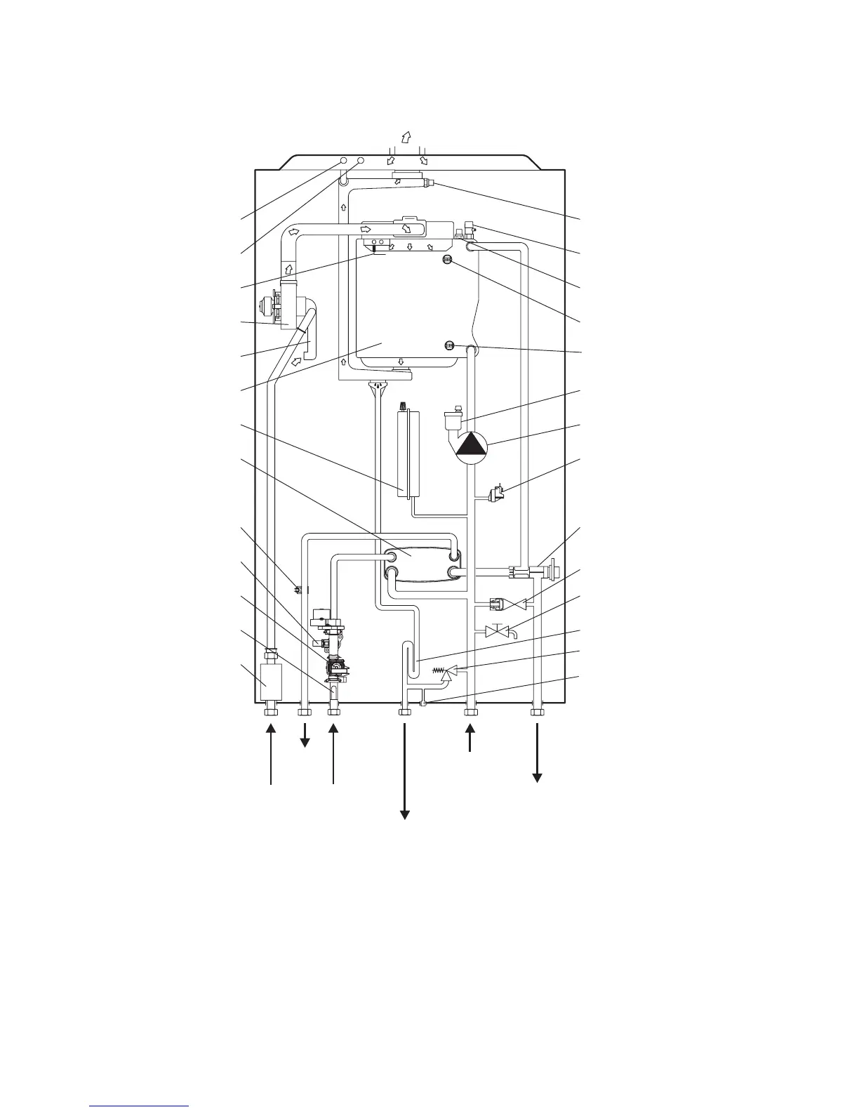
2.7 BOILER SCHEMATIC
1 - Gas valve
2 - Cold water filter
3 - DHW flow regulator
4 - Mains inlet sensor
5 - DHW sensor
6 - DHW heat exchanger
7 - Expansion vessel
8 - Primary heat exchanger
9 - Air/gas mixer
Fig. 2.4
10 - Fan
11 - Ignition/detection electrode
12 - Air test point (pressure point -)
13 - Flue test point (pressure point +)
14 - Flue temperature sensor
15 - Manual air vent
16 - Primary temperature sensor
17 - Overheat thermostat
18 - Return thermostat
19 - Automatic air vent
20 - Pump
21 - Primary pressure switch
22 - Diverter valve
23 - Automatic bypass
24 - Drain point
25 - Safety valve indicator
26 - Safety valve
27 - Safety valve indicator
Alpha InTec² 26E, 30CE and 35CE - Technical Data
Gas
Condensate discharge
and expansion relief
Primary
Heating
return
Primary
Heating flow
Domestic
hot water
outlet
Cold mains
water inlet
14
15
16
17
18
19
20
21
22
23
24
25
26
27
13
12
11
10
9
8
7
6
5
4
3
2
1
F(+) A(-)