33
Alpha InTec² 26E, 30CE and 35CE - Commissioning
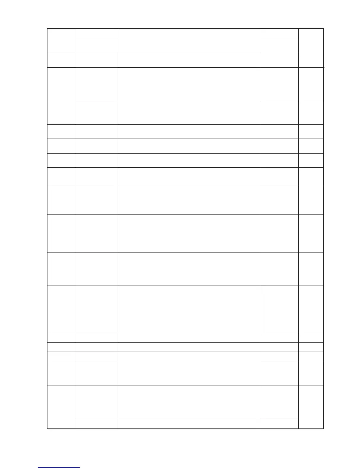
Parameter Feature Description Range
20 - 50 °C
(t0 + 5) + 85 °C
0 - 3
0 - 30 seconds
0 - 100 seconds
(10 sec steps)
0 - 600 seconds
(10 sec steps)
0 - 840 seconds
(10 sec steps)
0 - 600 seconds
(10 sec steps)
0 - 2
0 - 1
0 - 4
0, 8, 10, 12, 14,
16, A, AH
Set 3
1 - 9
1 - A3
0 - 25
0 - 2
-
Defines the minimum flow temperature set point
Defines the maximum flow temperature set point
Establishes the switch-off method in DHW mode at flow rates below
the minimum modulation level
1 and 3 correlated - The boiler switches off according to the
temperature set (this will cause cycling at low flow rate conditions)
0 and 2 fixed - The switch-off temperature is fixed at the maximum
(65 °C) value regardless of the value set on the control panel
The boiler is set to switch-on immediately with a request for DHW. If a
solar or other renewable cylinder is connected to pre-feed the boiler,
it is possible to delay firing the boiler in order to allow the pre-heated
water to reach the boiler
This sets a time delay for the boiler to switch back to CH mode after a
hot tap is closed
Adjustable anti-cycling period
Adjustable time period for the burner to ramp up to maximum output in
CH mode
Ignition response adjustment, ie underfloor type systems with slow
acting actuator valves will need a delay to prevent boiler overheating
occurring
Establishes the display lighting mode
0 Automatic - The display lights up during use and dims after 15 secs
of inactivity. In the event of an anomaly the display flashes
1 Low - The display is always lit with low intensity
2 High - The display is always lit with high intensity
'Summer' mode
0 - No information is displayed
1 - DHW active, the display shows the flow temperature
'Winter' mode
0 - The display shows the set value of the CH selector
1 - CH or DHW active, the display shows the flow temperature and
when not active the display shows the set value of the CH selector
Defines the type of hydraulics in the boiler
0 = Boiler flow switch (not used on this model)
1 = Flow meter (not used on this model)
2 = System boiler (not used on this model)
3 = Flow switch and boost - pre-heat function (not used on this model)
4 = Flow meter and boost function - preheat function
The flow regulator valve can be set with different functioning modes
0 - open: it is fully open, this allows the maximum possible flow rate
8, 10, 12, 14, 16 - limited max flow rate: allows a maximum flow rate
corresponding to the value set in litre/min
A - Auto: Automatically adjusts the max flow rate to achieve the DHW
temperature set point
AH - Auto High: as Auto (A), but when the DHW temperature is set at
55°C or higher, the regulator valve sets the flow at 10 l/min for 26CE
and 30CE, and 16 l/min for 35CE
Defines the type of pump in the boiler
Max. pump speed proportional to heat output
Min. speed setting *Should not be below 5
Defines the automatic pump speed control mode (see Section 2.4)
0 PROPORTIONAL: ΔT =0°C, pump head proportional to heat output
5-25 CONSTANT ΔT: ΔT=5-25°C, the pump speed is controlled
automatically to keep a constant ΔT between heating flow and return
Defines the length of the flue
0 = < 4.5 m
1 = 4.5 - 9.0 m
2 = > 9.0 m
In the event of an alteration, anomaly 'E72' will be displayed and fast
calibration is required. See Section 5.13
Not used on this bolier model
CH set point min.
temperature
CH set point max.
temperature
DHW thermostat
Solar delay timing
DHW priority timing
CH ignitions timer
CH ramp timer
CH ignition delay
from controls
request
Display lighting
Display information
Hydraulic model
Flow regulator
valve setting
Pump model
Max. pump speed
Min. pump speed
Automatic pump
speed control
Equivalent flue
length
-
T0
T1
T2
T3
T4
T5
T6
T7
T8
T9
A0
A1
A2
A3
A4
A5
F0
F1
Default
20
85
2
0
2
(20 secs)
18
(180 secs)
18
(180 secs)
0
0
1
1
A
3
9*
5*
15
0
-