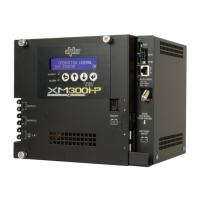
3. DOCSIS Communications Module
1. Connect the Battery Sense Harness to the A/B or C/D Connector (6). For XM3 units with the Smart AlphaGuard
(SAG) option, connect the Battery Harness to the SAG Connector (11) located on the left side of the XM3 Power
Supply.
2. Connect Tamper Switch Wire Harness to the TPR Connector (8).
3. Connect the RF drop to the RF Connector (7).
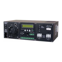
Front Panel Connections
To Battery Sense
Harnesses
TPR Connector
Required
Grounded Surge Protector
(Alpha p/n 162-028-10 or equivalent)
RF Cable
to Headend
RF Drop
7
8
6
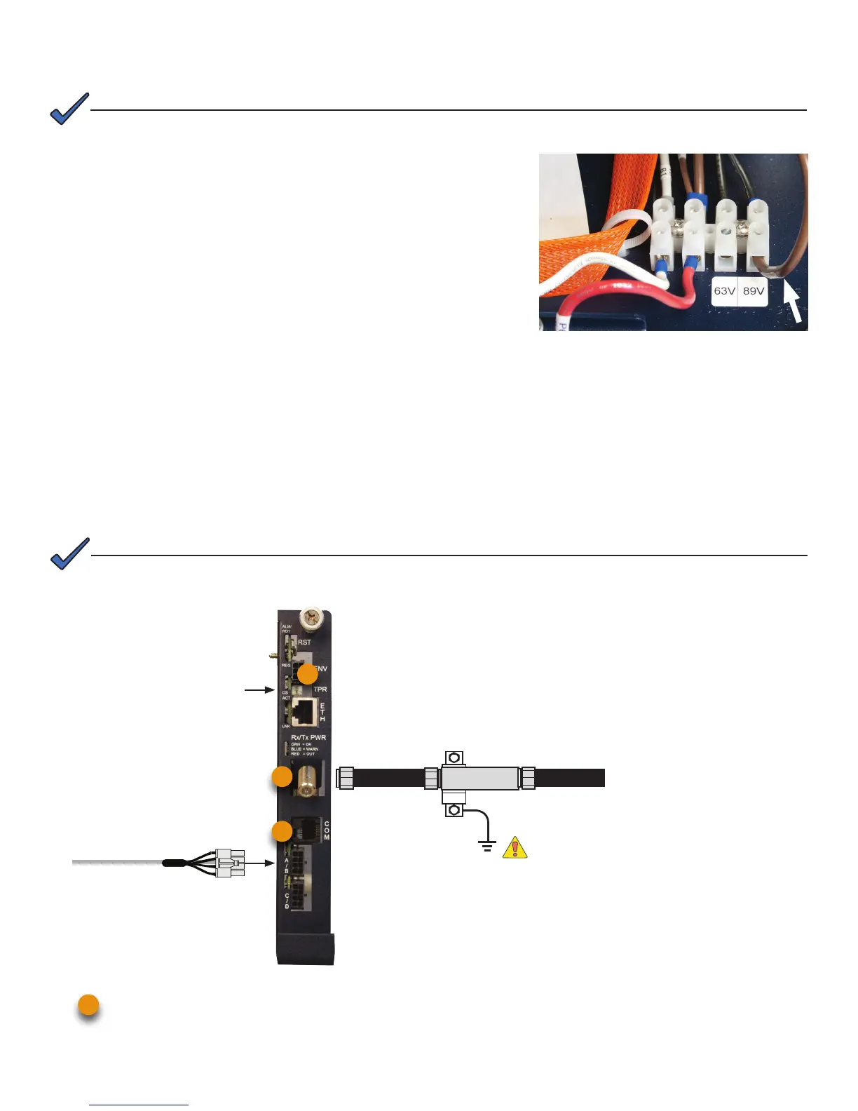
Some systems may require reconguring the output voltage setting. If necessary, follow the steps below to complete the
procedure. If the factory default satises your system requirements, proceed to Section 3.
2. Output Voltage Reconguration Procedure
Alpha DOCSIS Transponder (1 battery string) — use Battery Sense Harness, p/n 874-842-21.
Alpha DOCSIS Transponder (2 battery strings) — use Battery Sense Harness, p/n 874-842-28.
AlphaGuard (external) — use Battery Sense Harness, p/n 875-510-20 (S9) or p/n 875-510-21 (D9).
6
The output voltage factory default is 89 Volts.
NOTE:
The DOCSIS specication for downstream power level is 0 dBmV, +/- 15 dBmV. The upstream power level should not
exceed +50 dBmV.
NOTE:
Tools Required:
Small at-blade screwdriver.
1. To access output voltage terminal, remove the Inverter Module.
2. Loosen the terminal screw and move the output voltage wire (Fig. 1)
to the desired output voltage position on the terminal strip.
3. Torque the terminal block screw to 7 in-lbs. (0.79N-m) to secure the
output voltage wire.
4. Replace the Inverter Module.
Fig. 1 - Output voltage wire and terminal bar.