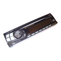
CDA-9853R
No. Symbol I/O Terminal Description
96 MP I Multi-Path signal input terminal.
97 AFC I AFC signal input terminal.
98 SSTOP I SEEK STOP input terminal.
99 S/M I TUNER S/M level input terminal.
100 NOSE DET I NOSE installation detect terminal.
No. Symbol I/O Terminal Description
1 ENCODER-1 I ENCODER input terminal.
2 NC - No connect terminal.
3 FRONT-SI I Serial data input terminal from Main u-COM.
4 FRONT-SO O Serial data output terminal to Main u-COM.
5 FRONT-CLK O Communication synchronous clock output terminal to Main u-COM.
6 EVdd - Power supply terminal for input/output ports.
7 EVss - GND terminal for input/output ports.
8 AMB CONT O Amber light control terminal.
9 GRN CONT O Green light control terminal.
10
I
17
18 Vpp I High-voltage impression terminal at writing.
19
I
30
31 RESET I System reset input terminal.
32
33
34 REGC - Capacitor connect terminal for regulator.
35 X2
36 X1
37 Vss - GND terminal for clock.
38 Vdd - Power supply terminal for clock.
39
I
43
44 DIMMER1
45 DIMMER2
46
I
54
55 BVdd - Power supply terminal for bus interface.
56 BVss - GND terminal for bus interface.
57
I
65
NC - No connect terminal.
NC - No connect terminal.
NC(PULL-DOWN) - Pull-down connect terminal.
- Crystal connect terminal. (20MHz)
NC - No connect terminal.
O DIMMER level control terminal.
NC - No connect terminal.
NC - No connect terminal.
 Loading...