(3) Control Settings
Power Switch .............................................. ON Band Switch .............................. FM/MW/LW
Fader Control ........................... Center Position T-CORR ...................................... Non Effect
Balance Control ....................... Center Position EQ ....................................................... FLAT
Treble Control .......................... Center Position DEMO ................................................... OFF
Bass Contro ............................. Center Position Others ................................................... OFF
MX ................................................... Non Effect
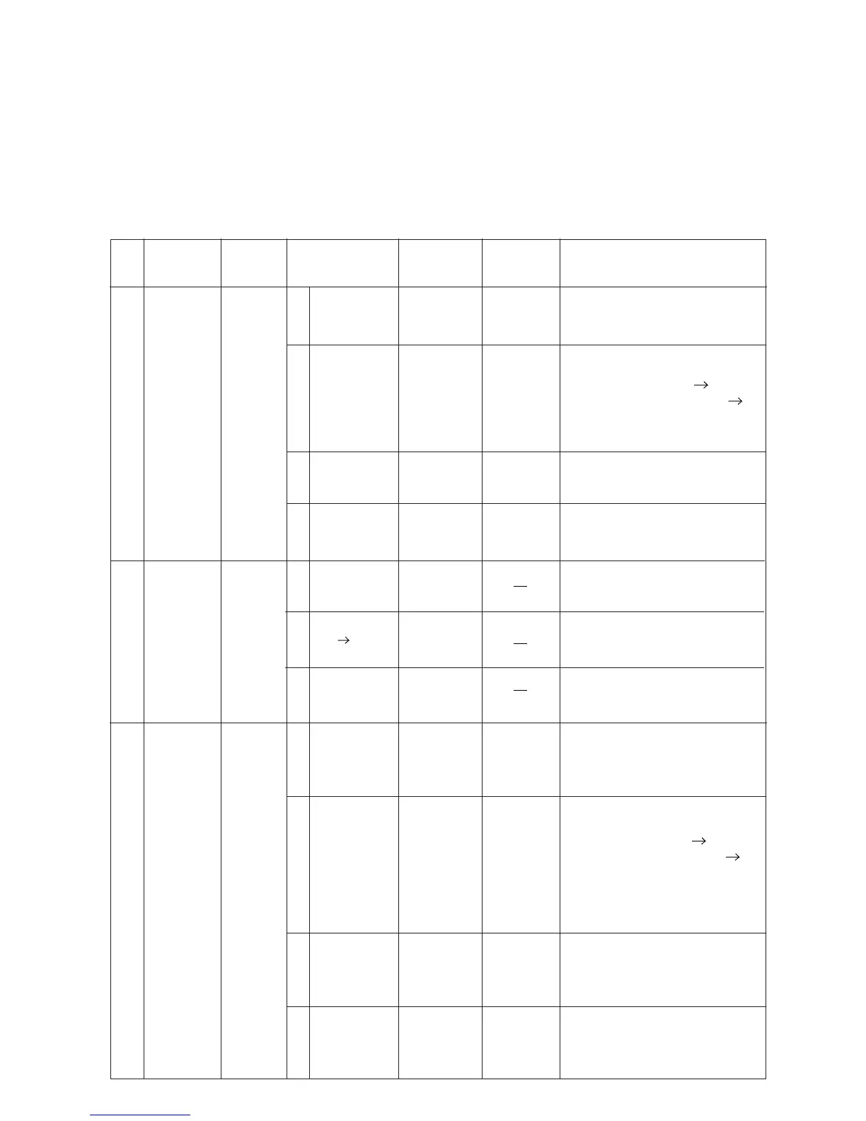
(4) Adjustment Procedures
Step Description
Connection
Signal Generator
Dial
Control
Test Point /
P.W.Board
Coordinates
Adjustment
1
Signal Meter
Auto
Adjustment
(FM)
Figure
3
(1)
87.5MHz,
26dBµ
(Mod. OFF)
87.5MHz
TP002
(3-F)
TP501
(3-F)
(2)
87.5MHz,
26dBµ
(Mod. OFF)
87.5MHz
TP002
(3-F)
TP501
(3-F)
(3)
87.5MHz,
21~23dBµ
(Mod. OFF)
87.5MHz
TP002
(3-F)
TP501
(3-F)
(4)
87.5MHz,
26dBµ
(Mod. OFF)
87.5MHz
TP002
(3-F)
TP501
(3-F)
Auto Adjustment:
After setting up of Signal Genarator,
short GND and TP501 (Pull-Down)
for 2~3 seconds.
Proceed same Auto Adjustment of step
(1) under step (2).
(SPEC) TP002 : 1.5±0.1V OK
(SPEC) TP002 : others 1.5±0.1V NG
NOTE : NG : Proceed same Auto
Adjustment of step (1)
under step (3).
Proceed same Auto Adjustment of step
(1) under step (3).
Proceed same Auto Adjustment of step
(1) under step (4).
3
Signal Meter
Auto
Adjustment
(MW)
Figure 4
(1)
999kHz,
34dBµ
(Mod. OFF)
(2)
999kHz,
34dBµ
(Mod. OFF)
(3)
999kHz,
29~31dBµ
(Mod. OFF)
(4)
999kHz,
34dB
(Mod. OFF)
µ
999kHz
999kHz
999kHz
999kHz
TP002
(3-F)
TP501
(3-F)
TP002
(3-F)
TP501
(3-F)
TP002
(3-F)
TP501
(3-F)
TP002
(3-F)
TP501
(3-F)
Auto Adjustment:
After setting up of Signal Genarator,
short GND and TP501 (Pull-Down)
for 2~3 seconds.
Proceed same Auto Adjustment of step
(1) under step (2).
(SPEC) TP002 : 1.0±0.1V OK
(SPEC) TP002 : others 1.0±0.1V NG
NOTE NG : Proceed same Auto
Adjustment of step (1)
under step (3).
Proceed same Auto Adjustment of step
(1) under step (3).
Proceed same Auto Adjustment of step
(1) under step (4).
:
2
Det Out-DC
OFFSET
Adjustment
(FM)
Figure
3
(1)
(2)
87.5MHz,
26dBµ
(Mod. OFF)
87.5MHz,
-20dB26 µ
(Mod. OFF)
87.5MHz,
-20dBµ
(Mod. OFF)
(3)
87.5MHz
87.5MHz
87.5MHz
" DC OFFSET " displays after finishing
S-METER (FM) adjustment.
The SIGNAL GENERATOR output of
26dBu is lowered to -20dBu within
10 seconds.
When adjustment is finished,the
" DC OFFSET " display disappears.
CDA-9855R