EasyManua.ls Logo

Alpine ERE-G180 - Service Manual

Alpine ERE-G180
21 pages
Print Icon
To Next Page IconTo Next Page
Loading...
JAP
INE.
SERVICE
MANUAL.
11-Band
Graphic
Equalizer
r
ie
5
PPO
ni
Fo.
Fase
leigiatetcialig
ER
E-GUsSome

Other manuals for Alpine ERE-G180

Question and Answer IconNeed help?

Do you have a question about the Alpine ERE-G180 and is the answer not in the manual?

Summary

Specifications

Connection Guide

Remote On Lead

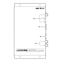
Connects to the head unit's remote turn-on lead for power activation.

Ground Lead

Connects to a good chassis ground for noise immunity and proper operation.

Battery Lead

Connects to the vehicle's positive battery terminal for power supply.

Basic System Setup

Speaker Output Connections

Diagram showing front, rear, and subwoofer output connections to amplifiers.

Phase and Stereo;Mono Switches

Explains the function of phase and stereo/mono switches for subwoofer setup.

Operational Guide

Power, Subwoofer, and Equalizer Control

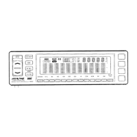
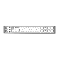
Covers turning the unit on/off, adjusting subwoofer level, and equalizer/defeat controls.

Volume, Tone, Fader, and BBE Mode Adjustment

Details adjusting volume, tone, fader, and BBE sound enhancement mode.

Block Diagram

Parts Layout and Wiring Diagram (1;2)

Parts Layout and Wiring Diagram (2;2)

Schematic Diagram (1;2)

Schematic Diagram (1;2)

Electrical Parts List

Main P.C. Board ICs

List of integrated circuits for the Main P. C. Board.

Main P.C. Board Transistors

List of transistors for the Main P. C. Board.

Main P.C. Board Diodes

List of diodes for the Main P. C. Board.

Main P.C. Board Coils and Transformers

List of coils and transformers for the Main P. C. Board.

Main P.C. Board Switches

List of switches for the Main P. C. Board.

Main P.C. Board Capacitors

List of capacitors for the Main P. C. Board.

Control P.C. Board Components

Control P.C. Board ICs

List of integrated circuits for the Control P. C. Board.

Control P.C. Board Transistors

List of transistors for the Control P. C. Board.

Packing Assembly Parts List

Miscellaneous Parts

Lists miscellaneous parts like connectors, LEDs, and volume controls.

Packing Method View

Visual guide showing how the unit is packed for shipping.

Exploded View (Cabinet)

Cabinet Assembly Parts List

Overview

This document is a service manual for the Alpine ERE-G180, an 11-Band Graphic Equalizer. It provides detailed information for technicians and users, covering specifications, connections, operation, and parts.

Function Description

The Alpine ERE-G180 is an 11-band graphic equalizer designed to provide precise control over audio frequencies in a car audio system. It allows users to adjust the sound profile to their preference and compensate for the acoustical characteristics of the vehicle's interior. In addition to equalization, the device integrates a BBE (Bass Boost Enhancement) mode for enhanced bass, a subwoofer output with adjustable crossover frequency and level, and phase control for optimal subwoofer integration. It also includes a fader control to balance front and rear speaker outputs.

Important Technical Specifications

  • Power Supply: DC14.4V (operating range 11-16V)
  • Total Harmonic Distortion (2Vrms/Channel): 0.1%
  • Input Sensitivity (Ref. 2V Output)/Impedance: 0±3dB/10k ohm
  • Output Impedance: 1k ohm
  • S/N Ratio (IHF-A): BBE OFF: 90dB, BBE ON: 85dB
  • Frequency Response (Ref. 1kHz, 30Hz~30kHz): 0±1dB
  • Channel Crosstalk Attenuation: 60dB
  • Current Drain (2V/Channel): 550mA
  • Fader Control Effect: 50dB
  • Equalizer Band Frequencies: 31.5, 63, 125, 190, 250, 500, 1k, 2.2k, 4.5k, 9k, 18kHz
  • Frequency Shaping Equalizer Controls: Boost: +11+3, -6dB; Cut: -11+3, -6dB
  • Channel Unbalance: 0+3dB
  • Subwoofer Cut-off Frequency Response (20Hz, 2V Output, Ref. -3dB): 42±10Hz, 150±25Hz
  • Subwoofer Control Effect (at 20Hz, Input 200mV): 15±3dB
  • Semi-Conductors: 21 IC's, 36 Transistors, 17 Diodes, 5 Zener Diodes, 1 FET
  • Dimensions (WxHxD): Chassis: 178×25×115mm; Nose: 178×25×17mm
  • Weight: 0.64kg

Usage Features

The ERE-G180 offers several user-friendly features for sound customization:

  • Power On/Off: The unit automatically turns on and off with the head unit.
  • Subwoofer Control:
    • Subwoofer Level: Adjustable up to +15 dB.
    • Crossover Frequency: Continuously adjustable between 50 Hz and 120 Hz.
    • STEREO/MONO Switch: Allows summing input for a single subwoofer or providing sound separation for multiple subwoofers.
    • PHASE Switch (0°/180°): Helps optimize bass response by compensating for standing waves in different car acoustical environments. Users can listen and switch to find the best bass response.
    • Subwoofer ON/OFF Switch: Engages or disengages the subwoofer mode. When OFF, front and rear outputs are full-range; when ON, front and rear outputs are high-pass, and the subwoofer output receives low-pass signals.
  • Volume/Tone/Fader Controls: Allows adjustment of overall volume, tone, and front/rear speaker balance. Output level indicators provide visual feedback, with a red LED indicating potential distortion if lit continuously.
  • BBE Mode: A dedicated switch toggles the BBE mode on or off, indicated by an amber LED when active, for enhanced bass.
  • Equalizer and Defeat Controls:
    • 11-Band Graphic Equalizer: Provides detailed frequency shaping.
    • EQUALIZER DEFEAT Switch: When "OFF" (green LED), all equalizer settings are active. When "ON" (amber LED), equalizer settings are bypassed (except for BBE if active).

Maintenance Features

The manual includes several sections valuable for maintenance and troubleshooting:

  • Connections/Connexions/Conexiones: Detailed wiring diagrams for power (remote on, ground, battery) and audio inputs/outputs, ensuring correct installation.
  • Block Diagram: An overview of the internal signal flow and component interconnections, useful for understanding the device's architecture and diagnosing issues.
  • Parts Layout on P.C. Boards and Wiring Diagram (1/2) & (2/2): Visual guides showing the placement of components on the printed circuit boards, viewed from the soldered side. These are critical for identifying components during repair.
  • Schematic Diagram (1/2) & (2/2): Detailed circuit diagrams illustrating the electrical connections and values of all components, essential for in-depth troubleshooting and component replacement.
  • Electrical Parts List: A comprehensive list of all electrical components, including their part numbers, descriptions (e.g., resistor, capacitor, IC, transistor, diode, switch, coil, transformer), and specifications. This is crucial for ordering replacement parts.
  • Packing Assembly Parts List & Packing Method View: Details related to the device's packaging, useful for understanding how the unit is assembled and for re-packaging if needed.
  • Exploded View (Cabinet) & Cabinet Assembly Parts List: Diagrams and lists showing the mechanical parts of the cabinet, aiding in disassembly and reassembly for repairs or modifications.

The manual also notes that specifications and designs are subject to change without notice due to continuous product improvement. Resistors under 1/4 watt are not listed in the parts list and should be confirmed via the schematic diagram. Capacitor values are specified in microfarads (µF) and picofarads (pF).

Alpine ERE-G180 Specifications

General IconGeneral
BrandAlpine
ModelERE-G180
CategoryStereo Equalizer
LanguageEnglish

Related product manuals