Do you have a question about the Alpine 3342 and is the answer not in the manual?
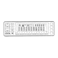
Details the buttons, displays, and indicators on the front control unit.
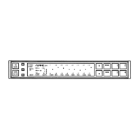
Lists the connectors, switches, and indicators on the rear base unit.
Describes RCA line output, input, and subwoofer connectors.
Controls for subwoofer phase and stereo/mono output selection.
Connects power, remote turn-on, ground, and defeat signal leads.
Specifies the 3A fuse rating for the unit.
Mounting the control unit using Velcro tape or an in-dash kit.
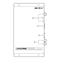
Mounting the base unit using mounting screws or Velcro tape.
Introduces Alpine's commitment to sound quality and the 3342 equalizer.
Recommends using other high-quality Alpine components for optimal performance.
Covers safe wiring, battery connection, mounting, and fuse replacement.
Creates 8 different listening environments using Digital Signal Processing.
Compensates for harmonic time alignment loss for crisp sound.
Details subwoofer output, level control, and phase switching.
Features 8 factory and 8 user-programmable presets, plus Memory Scan.
Includes remote power, display select, backlighting, and RCA connectors.
Use Level Control buttons to adjust Volume, Fader, and Balance.
Use Level Control buttons to adjust the subwoofer level.
Press ILLUM button to change illumination color between amber and green.
Press SCAN button to automatically scan factory presets.
Describes 8 DSP surround settings like Normal, Disco, Hall, Stadium, Church, Live.
Use M. SEL button to select MEMO 1 or MEMO 2 for presets.
Press Preset buttons (1-4) to select the desired pattern.
Press BBE button to activate; levels 1, 2, 3 offer decreasing effects.
Details 8 factory-set equalization curves for different music types.
Press DISP button repeatedly to select from 10 display modes.
Procedure to set and memorize user-programmable equalization curves and surround settings.
Keep equipment away from the car harness to prevent noise.
Keep power system and signal system separate to avoid noise interference.
A power supply filter is the first step in preventing noise from the power line.
The quality of the ground connection significantly affects noise levels.
Mount the control unit using double-sided adhesive Velcro tape.
Install the control unit in a DIN opening using the 4107 mounting kit.
Mount the base unit in the trunk room using provided mounting screws.
Mount the base unit using Velcro tape, similar to the control unit.
| Brand | Alpine |
|---|---|
| Model | 3342 |
| Category | Stereo Equalizer |
| Language | English |