ALPINE R2-A75M/R2-A60F 68-44781Z33-B (EN/DE/FR/ES/IT/SE/RU/CS)ALPINE R2-A75M/R2-A60F 68-44781Z33-B (EN/DE/FR/ES/IT/SE/RU/CS)
14-EN
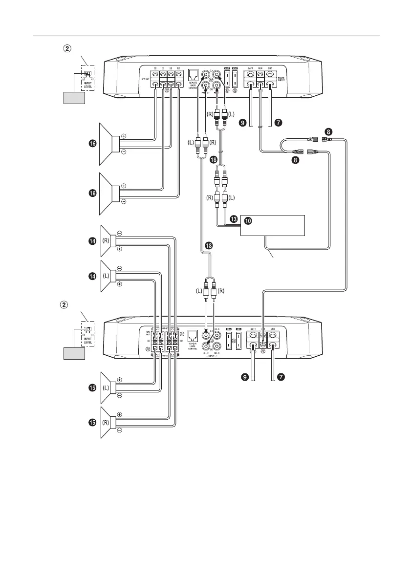
4 Speaker + Subwoofer / 2 Amplifier System (Connection example with R2-A60F)
[LO]
[LO]
Head Unit, etc.
(Top inner panel)
(Top inner panel)
Remote Turn-On Lead
Input Level Switch
Input Level Switch
R2-A75M
R2-A60F
• For details on the connection of R2-A60F, see “Basic Connection Diagram for R2-A60F” (page 15).
Basic Connection Diagram for R2-A60F
Speaker Output Terminals
Remote Bass Control (optional)
Pre-Out Jacks
RCA Input Jacks
Fuse
Power Supply Terminal
Ground Lead (sold separately)
Remote Turn-On Lead (sold separately)
Battery Lead (sold separately)
Head Unit, etc.
Front Output
For R2-A60F, change the Input Channel Selector Switch ( ) setting according to the number of channels of
the speaker input.
4-Channel Input: 2-Channel Input:
Input Channel Selector Switch
(CHANNEL-3/4)
3/4
1/2
4 Speaker System
[LO]
Head Unit, etc.
Remote Turn-On Lead
(Top inner panel)
Input Level Switch
* If the connected head unit does not have an RCA Output and RCA Extension Cable ( ) cannot be used,
you can use the Speaker-RCA Conversion Cable ( ) (sold separately). For details on how to make a
connection, see “About Connecting to the Speaker Input Level System” (page 19).