EasyManua.ls Logo

Alpine X-A90M - User Manual

Alpine X-A90M
28 pages
Print Icon
To Next Page IconTo Next Page
Loading...
EN
FR
ES
FOR CAR USE ONLY/POUR APPLICATION AUTOMOBILE/PARA USO EN AUTOMÓVILES
OWNER’S MANUAL
Please read before using this equipment.
MODE D’EMPLOI
Veuillez lire avant dutiliser cet appareil.
MANUAL DE OPERACIÓN
Léalo antes de utilizar este equipo.
ALPINE ELECTRONICS MARKETING, INC.
1-7, Yukigaya-Otsukamachi, Ota-ku,
Tokyo 145-0067, JAPAN
Phone: 03-5499-4531
ALPINE ELECTRONICS OF AMERICA, INC.
19145 Gramercy Place, Torrance,
California 90501, U.S.A.
Phone 1-800-ALPINE-1 (1-800-257-4631)
ALPINE ELECTRONICS OF AUSTRALIA PTY. LTD.
161-165 Princes Highway, Hallam
Victoria 3803, Australia
Phone 03-8787-1200
ALPINE ELECTRONICS GmbH
Wilhelm-Wagenfeld-Str. 1-3,
80807 München, Germany
Phone 089-32 42 640
ALPINE ELECTRONICS OF U.K. LTD.
Alpine House
Fletchamstead Highway, Coventry CV4 9TW, U.K.
www.alpine.co.uk
ALPINE ELECTRONICS France S.A.R.L.
184 allée des Erables
CS 52016 – Villepinte
95 945 Roissy CDG cedex
FRANCE
Phone : + 33(0)1 48 63 89 89
ALPINE ITALIA S.p.A.
Viale Cristoforo Colombo, 8
20090 Trezzano sul Naviglio MI, Italy
Phone +39 02 484781
ALPINE ELECTRONICS DE ESPAÑA, S.A.
Portal de Gamarra 36, Pabellón, 32
01013 Vitoria (Alava)-APDO 133, Spain
Phone 945-283588
X-A90M
MONO POWER AMPLIFIER
X-A70F
4 CHANNEL POWER AMPLIFIER
X-A90V
4 CHANNEL + MONO POWER AMPLIFIER
JEIL Moon Hwa Co.
18-6, 3Ga, Pil_dong, Jung_gu, Seoul, Korea
Designed by ALPINE Japan
Printed in Korea
68-33122Z89-A (Y-A5)
M3514640010
Question and Answer IconNeed help?

Do you have a question about the Alpine X-A90M and is the answer not in the manual?

Summary

WARNING

Points to Observe for Safe Usage

Key instructions for safe and effective use of the system components, emphasizing adherence to manual guidelines.

INSTALLATION

Basic Connection Diagram for X-A90 M

Basic Connection Diagram for X-A70 F

Basic Connection Diagram for X-A90 V

Cautions on Power Supply Wires

X-A90 M Specifications

X-A70 F Specifications

X-A90 V Specifications

Overview

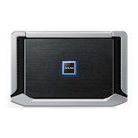
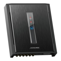
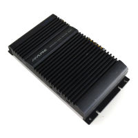
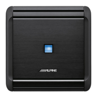
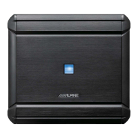
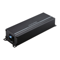
This document describes the Alpine X-A90M, X-A70F, and X-A90V power amplifiers, providing detailed information on their functions, technical specifications, usage, and maintenance.

Function Description:

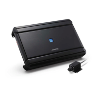
The Alpine X-A90M is a mono power amplifier, the X-A70F is a 4-channel power amplifier, and the X-A90V is a 4-channel plus mono power amplifier. These amplifiers are designed for car audio systems, enhancing the audio output from a head unit to speakers and subwoofers. They feature various controls for fine-tuning audio performance, including input gain adjustment, crossover settings, and bass equalization. The amplifiers are built to produce significant power output, necessitating proper installation for heat dissipation.

Important Technical Specifications:

X-A90M (Mono Power Amplifier):

  • Power Output:
    • 600 W RMS x 1 (Per Channel, Ref.: 4 Ω, 14.4 V)
    • 900 W RMS x 1 (Per Channel, Ref.: 2 Ω, 14.4 V)
  • THD+N:
    • ≤0.02% (Ref.: 10 W into 4 Ω)
    • ≤0.07% (Ref.: Rated Power into 4 Ω)
  • S/N Ratio:
    • 83 dB (IHF A-wtd + AES-17, Ref.: 1W into 4 Ω)

    • 107 dB (IHF A-wtd + AES-17, Ref.: Rated Power into 4 Ω)

  • Frequency Response:
    • 8 Hz - 400 Hz (+0/-3 dB, Ref.: 1 W into 4 Ω)
    • 10 Hz - 300 Hz (+0/-1 dB, Ref.: 1 W into 4 Ω)
  • Damping Factor: >1,500 (Ref.: 10 W into 4 Ω at 100 Hz)
  • Input Sensitivity:
    • Hi: 0.4 - 10 V (RCA Input)
    • Lo: 0.1 - 4.0 V (RCA Input)
  • Crossover:
    • Variable LPF: 50 Hz - 400 Hz (-24 dB/oct.)
    • Variable Subsonic: 8 Hz - 40 Hz (-24 dB/oct.)
  • Equalizer: Bass EQ (fc=50 Hz) 0 to +12 dB (Variable)
  • Remote Level: Linear Attenuation 0 to -20 dB (Requires optional RUX-KNOB or RUX-KNOB.2)
  • Input Impedance: >10 kΩ
  • Preamp Output: CH-1/2 Input Pass-through, Buffered (4 V max)
  • Dimensions:
    • Width: 297 mm (11-3/4")
    • Height: 50.8 mm (2")
    • Depth: 192 mm (7-5/8")
  • Weight: 3.2 kg (7 lb 1 oz)

X-A70F (4-Channel Power Amplifier):

  • Power Output:
    • 120 W RMS x 4 (Per Channel, Ref.: 4 Ω, 14.4 V)
    • 175 W RMS x 4 (Per Channel, Ref.: 2 Ω, 14.4 V)
    • 350 W RMS x 2 (Bridged, Ref.: 4 Ω, 14.4 V)
  • THD+N:
    • ≤0.02% (Ref.: 10 W into 4 Ω)
    • ≤0.07% (Ref.: Rated Power into 4 Ω)
  • S/N Ratio:
    • 87 dB (IHF A-wtd + AES-17, Ref.: 1W into 4 Ω)

    • 106 dB (IHF A-wtd + AES-17, Ref.: Rated Power into 4 Ω)

  • Frequency Response:
    • 10 Hz - 60 kHz (+0/-3 dB, Ref.: 1 W into 4 Ω)
    • 15 Hz - 30 kHz (+0/-1 dB, Ref.: 1 W into 4 Ω)
  • Damping Factor: >500 (Ref.: 10 W into 4 Ω at 100 Hz)
  • Input Select: Selectable Input Signal Configuration (2ch/4ch Input)
  • Input Sensitivity:
    • Hi: 0.5 - 10 V (RCA Input)
    • Lo: 0.2 - 4.0 V (RCA Input)
  • Crossover: Variable HPF/LPF: 50 Hz - 400 Hz (-12 dB/oct.)
  • Remote Level: Linear Attenuation 0 to -20 dB (Requires optional RUX-KNOB.2)
  • Input Impedance: >10 kΩ
  • Dimensions:
    • Width: 297 mm (11-3/4")
    • Height: 50.8 mm (2")
    • Depth: 192 mm (7-5/8")
  • Weight: 3.2 kg (7 lb 1 oz)

X-A90V (4-Channel + Mono Power Amplifier):

  • Power Output (CH-1/2/3/4):
    • 75 W RMS x 4 (Per Channel, Ref.: 4 Ω, 14.4 V)
    • 100 W RMS x 4 (Per Channel, Ref.: 2 Ω, 14.4 V)
    • 200 W RMS x 2 (Bridged, Ref.: 4 Ω, 14.4 V)
  • Power Output (SUBWOOFER):
    • 300 W RMS x 1 (Per Channel, Ref.: 4 Ω, 14.4 V)
    • 500 W RMS x 1 (Per Channel, Ref.: 2 Ω, 14.4 V)
  • THD+N (CH-1/2/3/4):
    • ≤0.02% (Ref.: 10 W into 4 Ω)
    • ≤0.07% (Ref.: Rated Power into 4 Ω)
  • THD+N (SUBWOOFER):
    • ≤0.02% (Ref.: 10 W into 4 Ω)
    • ≤0.07% (Ref.: Rated Power into 4 Ω)
  • S/N Ratio (CH-1/2/3/4):
    • 87 dB (IHF A-wtd + AES-17, Ref.: 1W into 4 Ω)

    • 105 dB (IHF A-wtd + AES-17, Ref.: Rated Power into 4 Ω)

  • S/N Ratio (SUBWOOFER):
    • 80 dB (IHF A-wtd + AES-17, Ref.: 1W into 4 Ω)

    • 104 dB (IHF A-wtd + AES-17, Ref.: Rated Power into 4 Ω)

  • Frequency Response (CH-1/2/3/4):
    • 10 Hz - 60 kHz (+0/-3 dB, Ref.: 1 W into 4 Ω)
    • 15 Hz - 30 kHz (+0/-1 dB, Ref.: 1 W into 4 Ω)
  • Frequency Response (SUBWOOFER):
    • 8 Hz - 400 Hz (+0/-3 dB, Ref.: 1 W into 4 Ω)
    • 10 Hz - 300 Hz (+0/-1 dB, Ref.: 1 W into 4 Ω)
  • Damping Factor (CH-1/2/3/4): >500 (Ref.: 10 W into 4 Ω at 100 Hz)
  • Damping Factor (SUBWOOFER): >1,000 (Ref.: 10 W into 4 Ω at 100 Hz)
  • Input Select: Selectable Input Signal Configuration (2ch/4ch/6ch Input)
  • Input Sensitivity (CH-1/2/3/4):
    • Hi: 0.5 - 10 V (RCA Input)
    • Lo: 0.2 - 4.0 V (RCA Input)
  • Input Sensitivity (SUBWOOFER):
    • Hi: 0.4 - 10 V (RCA Input)
    • Lo: 0.1 - 4.0 V (RCA Input)
  • Crossover (CH-1/2/3/4): Variable HPF/LPF: 50 Hz - 400 Hz (-12 dB/oct.)
  • Crossover (SUBWOOFER): Variable LPF: 50 Hz - 400 Hz (-24 dB/oct.)
  • Variable Subsonic (SUBWOOFER): 8 Hz - 40 Hz (-24 dB/oct.)
  • Equalizer (SUBWOOFER): Bass EQ (fc=50 Hz) 0 to +12 dB (Variable)
  • Remote Level: Linear Attenuation 0 to -20 dB (Requires optional RUX-KNOB or RUX-KNOB.2)
  • Input Impedance: >10 kΩ
  • Dimensions:
    • Width: 297 mm (11-3/4")
    • Height: 50.8 mm (2")
    • Depth: 192 mm (7-5/8")
  • Weight: 3.3 kg (7 lb 4 oz)

Usage Features:

  • Installation: The amplifiers generate considerable heat during operation, so they must be mounted in a location that allows for free air circulation, such as inside the trunk. The installation process involves marking screw locations, drilling holes, and securing the amplifier with self-tapping screws. Terminal covers and a logo plate are attached after connections are made.
  • Top Cover Removal: The top cover must be removed to access the switch settings. This involves removing hexagon screws and sliding off the cover. Care must be taken not to damage the indicator area.
  • Connections: Before making any connections, the power to all audio components must be turned off. Connections include power supply (battery, remote turn-on, ground), RCA input jacks from the head unit, and speaker output terminals. Speaker input level switches (LO/HI) are provided for different input types (RCA extension cables or speaker-RCA conversion cables).
  • Power Supply Wiring: Specific wire sizes are recommended based on the total fuse capacity of the amplifier and wire length. An external fuse (e.g., fuse block, circuit breaker) must be added as close as possible to the battery's positive terminal to protect the vehicle's electrical system. Ground leads should be connected securely to a clean, bare metal spot on the vehicle's chassis.
  • Remote Turn-On Lead: This lead connects to the head unit's remote turn-on (positive trigger, +12V only) lead. If a remote turn-on lead is unavailable, the amplifier can be connected to a switched power source (ignition) with a 3A fuse. An optional SPST switch can be installed in-line to manually control power.
  • Speaker Output Connections: Speaker output leads are connected to the speaker connector, ensuring correct polarity. Bridged connections are possible for higher power output to a single speaker or subwoofer.
  • Subwoofer Input/Output (X-A90M/X-A90V only): The input is stereo, but the output is monaural. Reversing subwoofer polarity may be desirable for optimum bass performance.
  • Switch Settings:
    • Subsonic Filter (X-A90M/X-A90V only): Cuts ultra-low frequencies to protect speakers, minimize wasted power, and prevent subwoofer over-excursion in vented enclosures.
    • Crossover Frequency Adjustment Knob (LP FILTER) (X-A90M/X-A90V only): Adjusts the crossover frequency between 50 to 400 Hz.
    • Bass EQ Adjustment Knob (X-A90M/X-A90V only): Adds a 50 Hz bass boost up to +12 dB.
    • Input Gain Adjustment Control: Sets the amplifier's input gain to match the head unit's output, preventing distortion.
    • Crossover Mode Selector Switch (X-A70F/X-A90V only): Selects between OFF (full range), HP (high-pass for tweeters/midrange), or LP (low-pass for subwoofers) modes.
    • Input Channel Selector Switch (CHANNEL-3/4 for X-A70F/X-A90V, SUBWOOFER for X-A90V): Configures input mode (2-channel, 4-channel, or 6-channel for X-A90V) and signal routing to channels or subwoofer.
  • Power Indicator: A blue light indicates normal operation. A blinking red light indicates high operating temperature. A solid red light indicates an abnormal circuit, electrical short, high supply current, or high power supply voltage. Solutions are provided for each red light scenario.

Maintenance Features:

  • General Care: The manual emphasizes reading all instructions carefully to ensure safe and effective use. Alpine is not responsible for problems resulting from failure to observe these instructions.
  • Safety Precautions:
    • Do not disassemble or alter the unit.
    • Use correct ampere rating for fuses.
    • Do not block vents or radiator panels.
    • Make correct connections.
    • Use only in cars with a 12-volt negative ground.
    • Disconnect the negative battery terminal before wiring.
    • Prevent cables from becoming entangled.
    • Do not splice into electrical cables.
    • Avoid damaging pipes or wiring when drilling holes.
    • Do not use brake or steering system bolts/nuts for ground connections.
    • Keep small objects (like batteries) out of reach of children.
    • Halt use immediately if a problem appears and consult an authorized dealer.
    • Have wiring and installation done by experts.
    • Use specified accessory parts and install them securely.
    • Arrange wiring to prevent crimping or pinching by sharp metal edges.
    • Avoid installing in locations with high moisture or dust.
  • Troubleshooting (Power Indicator): The power indicator provides visual cues for operational status. If a red light appears, specific actions are recommended, such as decreasing vehicle interior temperature, turning off power to eliminate shorts, or checking power supply voltage. If issues persist, consulting an Alpine dealer is advised.
  • Noise Prevention: To prevent external noise, locate the unit and route leads at least 10 cm (4") away from the vehicle's harness. Keep battery power leads away from other leads. Connect the ground lead securely to a bare metal spot on the chassis. Optional noise suppressors can be used, and an Alpine dealer can provide further information on noise prevention.
  • Warranty Information: The product comes with a limited warranty covering defects in materials or workmanship for one year from the purchase date. The warranty applies to the original purchaser residing in the United States, Puerto Rico, or Canada. Specific exclusions apply, such as damage from accidents, misuse, unauthorized service, or altered serial numbers. To obtain service, the product must be delivered to an authorized service center with proof of purchase and a detailed problem description.

The X-A90M, X-A70F, and X-A90V amplifiers are designed for high-quality car audio performance, offering robust power and extensive control over sound output, with clear guidelines for safe installation and operation.

Alpine X-A90M Specifications

General IconGeneral
BrandAlpine
ModelX-A90M
CategoryAmplifier
LanguageEnglish

Related product manuals