EasyManua.ls Logo

Alpine X-A90V User Manual

Alpine X-A90V
28 pages
To Next Page IconTo Next Page
Page #1 background imageLoading...
Page #1 background image
EN
FR
ES
FOR CAR USE ONLY/POUR APPLICATION AUTOMOBILE/PARA USO EN AUTOMÓVILES
OWNER’S MANUAL
Please read before using this equipment.
MODE D’EMPLOI
Veuillez lire avant dutiliser cet appareil.
MANUAL DE OPERACIÓN
Léalo antes de utilizar este equipo.
ALPINE ELECTRONICS MARKETING, INC.
1-7, Yukigaya-Otsukamachi, Ota-ku,
Tokyo 145-0067, JAPAN
Phone: 03-5499-4531
ALPINE ELECTRONICS OF AMERICA, INC.
19145 Gramercy Place, Torrance,
California 90501, U.S.A.
Phone 1-800-ALPINE-1 (1-800-257-4631)
ALPINE ELECTRONICS OF AUSTRALIA PTY. LTD.
161-165 Princes Highway, Hallam
Victoria 3803, Australia
Phone 03-8787-1200
ALPINE ELECTRONICS GmbH
Wilhelm-Wagenfeld-Str. 1-3,
80807 München, Germany
Phone 089-32 42 640
ALPINE ELECTRONICS OF U.K. LTD.
Alpine House
Fletchamstead Highway, Coventry CV4 9TW, U.K.
www.alpine.co.uk
ALPINE ELECTRONICS France S.A.R.L.
184 allée des Erables
CS 52016 – Villepinte
95 945 Roissy CDG cedex
FRANCE
Phone : + 33(0)1 48 63 89 89
ALPINE ITALIA S.p.A.
Viale Cristoforo Colombo, 8
20090 Trezzano sul Naviglio MI, Italy
Phone +39 02 484781
ALPINE ELECTRONICS DE ESPAÑA, S.A.
Portal de Gamarra 36, Pabellón, 32
01013 Vitoria (Alava)-APDO 133, Spain
Phone 945-283588
X-A90M
MONO POWER AMPLIFIER
X-A70F
4 CHANNEL POWER AMPLIFIER
X-A90V
4 CHANNEL + MONO POWER AMPLIFIER
JEIL Moon Hwa Co.
18-6, 3Ga, Pil_dong, Jung_gu, Seoul, Korea
Designed by ALPINE Japan
Printed in Korea
68-33122Z89-A (Y-A5)
M3514640010
Question and Answer IconNeed help?

Do you have a question about the Alpine X-A90V and is the answer not in the manual?

Alpine X-A90V Specifications

General IconGeneral
BrandAlpine
ModelX-A90V
CategoryAmplifier
LanguageEnglish

Summary

General Safety Precautions

Driving and Operational Safety

DO NOT OPERATE ANY FUNCTION THAT TAKES YOUR ATTENTION AWAY FROM SAFELY DRIVING YOUR VEHICLE. KEEP THE VOLUME AT A LEVEL WHERE YOU CAN STILL HEAR OUTSIDE NOISES WHILE DRIVING.

Electrical and Product Safety

DO NOT DISASSEMBLE OR ALTER. USE THE CORRECT AMPERE RATING WHEN REPLACING FUSES. USE THIS PRODUCT FOR MOBILE 12V APPLICATIONS. DO NOT BLOCK VENTS OR RADIATOR PANELS. MAKE THE CORRECT CONNECTIONS. USE ONLY IN CARS WITH A 12 VOLT NEGATIVE GROUND. BEFORE WIRING, DISCONNECT THE CABLE FROM THE NEGATIVE BATTERY TERMINAL. DO NOT ALLOW CABLES TO BECOME ENTANGLED IN SURROUNDING OBJECTS. DO NOT SPLICE INTO ELECTRICAL CABLES. DO NOT DAMAGE PIPE OR WIRING WHEN DRILLING HOLES.

Installation, Service, and Accessories

Installation and Handling Safety

Ensure safe installation practices, proper wiring, suitable environments, and child safety precautions.

Problem Handling, Expertise, and Parts

Halt use if problems occur, use experts for installation, secure parts, and be aware of environmental limits.

Amplifier Installation Guide

Mounting Location and Procedure

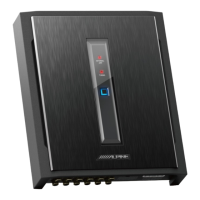
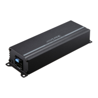
Mount the amplifier in a location allowing air circulation. Mark screw locations, ensure no objects behind surface, and drill holes.

Audio Connection Procedures

Pre-Connection Safety and Preparation

Turn off all audio components before connecting. Ensure secure connections for power, ground, and speaker leads.

Connection Details

Power Supply and Fuse Requirements

Check fuse capacity and install external fuse near battery's positive terminal.

Input Signal and Control Connections

Set Speaker Input Level Switch, connect RCA jacks, and use Pre-Out/Remote Bass Control features.

Speaker Output Connections

Connect speaker output leads to the Speaker Connector, observing correct polarity and channel assignment.

Advanced Connection Details

Bridged and Subwoofer Connection Modes

Subwoofer output is monaural. For bridged connections, link left positive to speaker positive, right negative to speaker negative.

Wire Lead Connection Procedures

Verify wire size and strip insulation from wire leads by 7-10 mm for proper connection.

Switch Settings and Controls

Advanced Switch Settings and Modes

Advanced Subwoofer and Multi-Amp Wiring

X-A70F System Wiring Diagrams

Bridged System Configurations

X-A90V System Wiring Diagrams

Advanced System Wiring Configurations

Speaker Input Level System Connection

Power Supply Wire Connection Guidelines

Wire Size and Fuse Capacity Selection

Select wire size based on total fuse capacity and length. Match external fuse capacity to amplifier's requirements.

Power Wire Connection Examples

Examples illustrate wire size and distribution block usage for single and multiple amplifier installations.

Power Wire Preparation

Properly prepare wire leads by removing insulation and twisting the core line for secure connections.

X-A90M Specifications

X-A70F Specifications

X-A90V Specifications

Power Supply Wire Connection Guide

Wire Size and Fuse Capacity Chart

Chart detailing wire size required based on fuse capacity and wire length for amplifier installations.

Power Wire Connection Best Practices

Properly prepare wire leads and ensure secure connections using appropriate terminals and screws.

Related product manuals