ALSATOM SU MPC series – SERVICE MANUAL
- alsa apparecchi medicali s.r.l. -
3
PRELIMINARY
PAY ATTENTION!! BEFORE TO CONNECT THE UNIT TO MAINS, CHECK MAINS VALUE ON REAR
SIDE ELECTRICAL DATA LABEL.
Remove F3 fuse – connected to power supply for HF output – placed on main board (alsa code 801336).
SETTING PROCEDURE
J11 connected to GND is needed to switch ON the unit in setting mode. To do this, a 100 ohms/ ¼ watts
resistors must be used. This avoids alarms due to setting not yet carried out or in case of troubleshooting.
After the unit is switched on, connection from J11 and GND can be removed, until the next switching on.
With the unit in setting mode, display shows different parameters according to what mode is selected to let to
monitoring the whole unit. Refers to the following table for shown parameters according to the mode selector.
Mode selector Cut display Coagulation display
Pure Cut HF output power setting Proportional signal to HF output power
Blend Cut HF output power setting Proportional signal
Macro Coag
Proportional signal to output waveform
modulation
HF output power setting
Micro Coag Proportional signal to mains HF output power setting
Bipolar Coag Proportional signal to HF output power
HF output power setting
+5V AND +15V LOW POWER SUPPLY CHECK
In setting mode, connect a multimeter in parallel to D28 (“TP1”) on main board. DC voltage must be +5V(±
0.2 V). Next connect multimeter to “TP2” and check DC voltage: this must be +15V(± 0.6 V).
D/A CONVERTER VOLTAGE REFERENCE CHECK
Connect multimeter to J8 (“TPA”) on microcontroller board and check if DC voltage is +5V (± 0.01V); set
voltage using R20 pot if required.
PAY ATTENTION!!! CARE SHOULD BE TAKEN TO SET THAT VOLTAGE! IF VOLTAGE REFERENCE
IS HIGHER THAN 5.1 V, MICROCONTROLLER COULD BE DAMAGED. IF SETTING IS REQUIRED,
REMOVE J8 JUMPER, SET REFERENCE VOLTAGE WITHOUT EXCEED THE ABOVE MENTIONED
LIMIT. AFTER PLACE J8 JUMPER IN ITS ORIGINAL POSITION.
SETTING OF NEUTRAL PLATE ALARM CIRCUIT
(not needed in SU 140/BD MPC)
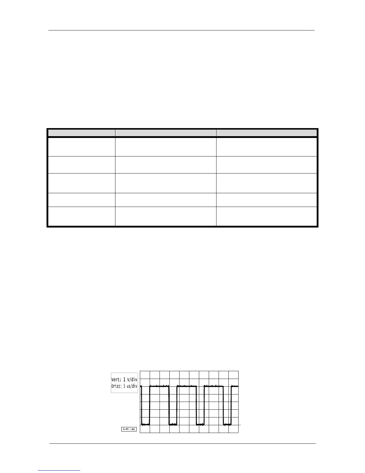
Connect the oscilloscope probe to “TPB” on microcontroller board; set R35 pot to obtain a 71 kHz (± 2 kHz)
square waveform.