ALSATOM SU MPC series – SERVICE MANUAL
- alsa apparecchi medicali s.r.l. -
5
To check correct pencil activation mode using a standard pencil. If no activation occurs, turn R75 pot slightly
counter clockwise. Moreover, pushing both pencil buttons at the same time unit must give alarm.
Switch the unit OFF and place F3 fuse in main board.
HF SECTION POWER SUPPLY CHECK
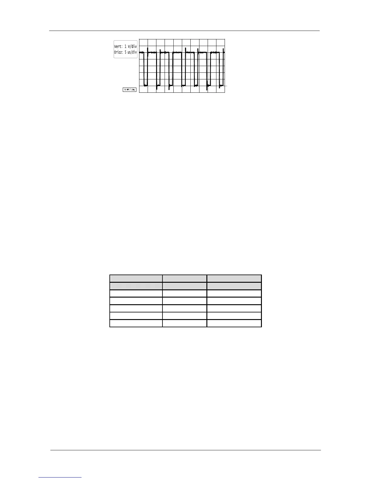
Switch ON the unit in setting mode.
Connect the multimeter to R18 placed on main board; check a +81V (± 5 V) DC voltage. This voltage can’t
be set.
SETTING OF MINIMUM AND MAXIMUM HF OUTPUT POWER LEVELS
Set 80 in CUT mode, connect a 500 ohms/200 Watts non-inductive load to monopolar output (in SU 140/BD
MPC load must be 400 ohms).
Start the unit: HF output current flowing in the load must be 400 mAmps (i.e. 80 Watts). In SU 140/BD MPC
current must be 440 mAmps.
If HF output current is different from the above mentioned value, turn R31 pot on microcontroller board.
Set 10 in CUT mode and start the unit.
Turn R39 pot on microcontroller board to obtain a HF output current of 145 mAmps (i.e. 10 Watts).
Since maximum and minimum settings are interactives, above mentioned steps must be performed two or
three times in order to obtain best setting.
SETTING OF I_LEAK SIGNAL
Start the unit in CUT mode setting up values in the following table and check corresponding values on COAG
section display.
All models SU 140/BD only
CUTsetting COAG Display COAG Display
5 5÷7
10 6÷7
50 38÷39 29÷30
80 58÷63 56÷57
100 79÷82 73÷77
Values can be obtained turning R41 pot placed on main board.
SETTING OF CURRENT LIMIT
Connect a 100 ohms/100 watts non-inductive load (load must be 10 ohms in SU 140/BD).
Start the unit in COAG mode and turn R45 pot placed on microcontroller board on current limit threshold
value. Once found this threshold, turn back the same pot slightly. Next, connect a 500ohms/100 watts non-
inductive load to check if current limit setting affected nominal load HF delivery power in all modes.
After this check switch OFF the unit.
0