ALSATOM SU MPC series – SERVICE MANUAL
- alsa apparecchi medicali s.r.l. -
4
Check the neutral plate alarm circuit using various resistors: with values higher than 100-200 ohms alarm
occurs. With values lower than 100 ohms the circuit doesn’t give alarm and the unit can be used.
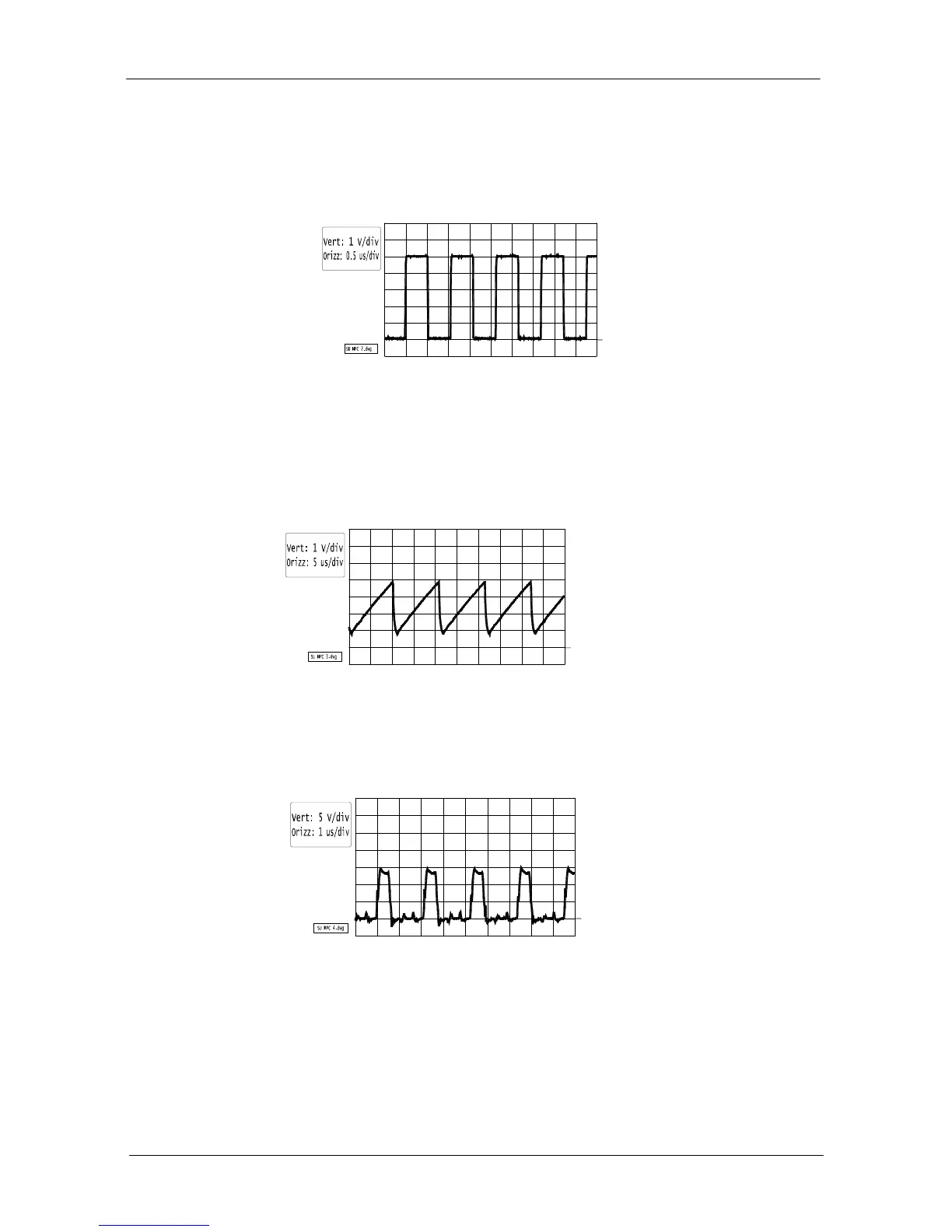
HF OUTPUT POWER FREQUENCY CHECK
Connect the oscilloscopi probe to “TPC” test point on microcontroller board and check a frequency of 938
kHz (± 5 kHz); waveform must be like the following:
SETTING OF RAMP DRIVING SIGNAL
Set the unit in CUT mode with power setting at its minimum level, connect the oscilloscope probe to “TPD”
test point; press the footswitch and set R31 pot in order to obtain the following waveform (ramp signal must
be set at 4 V exactly in all models with both monopolar and bipolar output; only in SU 140/BD MPC ramp
signal must be set at 4.120V).
HF OUTPUT MOSFETS DRIVING SIGNAL CHECK
Connect the oscilloscope probe at “TPE” test point.
Set power setting at its maximum level.
Activating the unit in CUT mode, check the following waveform:
SETTING OF SIGNAL TO ENABLE UNIT FROM HANDSWITCH WITH PUSHBUTTONS
(needed in SU140/D MPC and SU140 MPC only)
Connect the oscilloscope probe at “TP3” and check the following waveform:
0