pag. 30
MDE/C133 2561 001
MX3IPG2A
WARNING:
The factory settings may prove not to suit the system. Therefore, the device must be configured anew upon installation
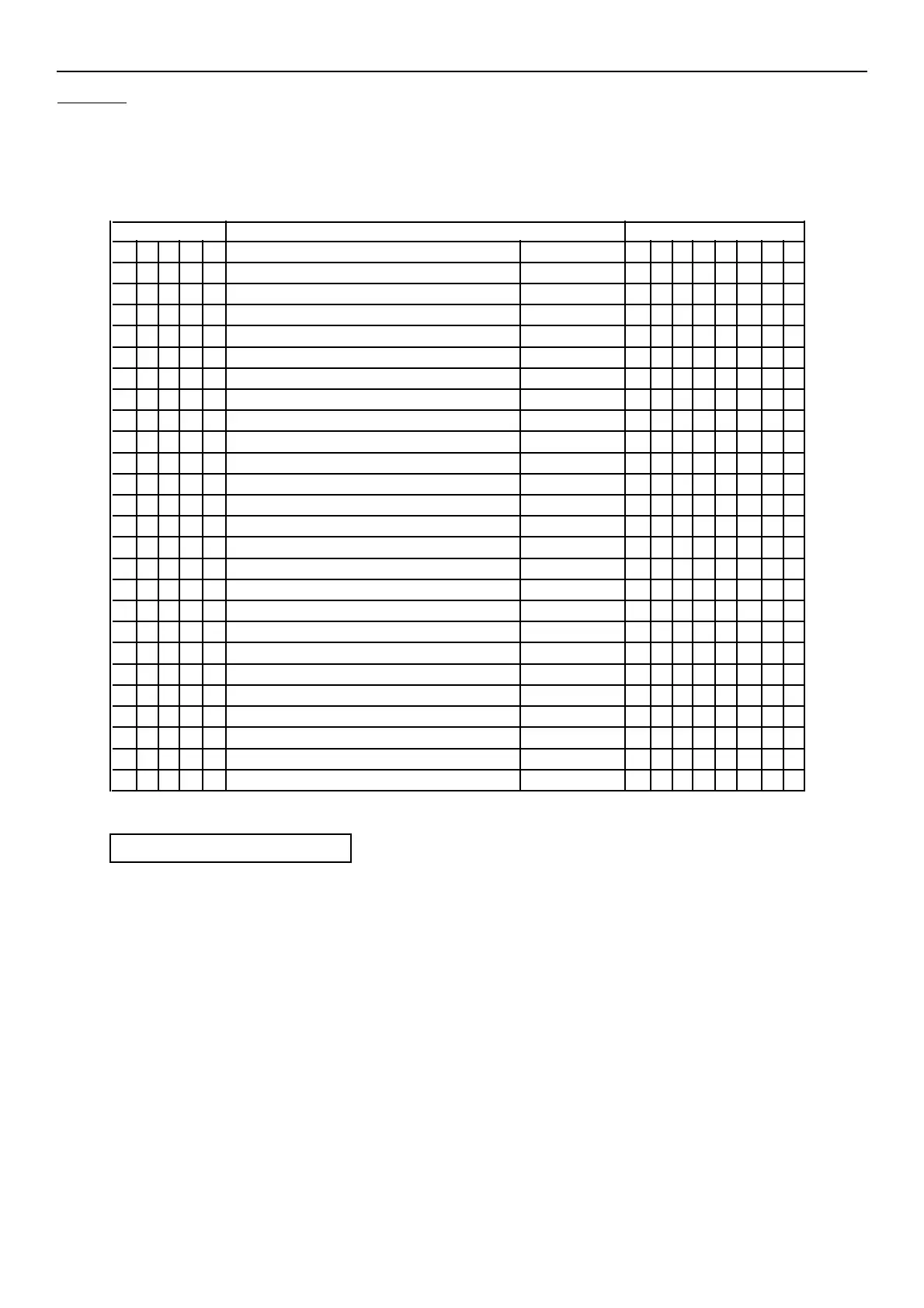
tab. A - FACTORY SETTINGS
RELAY CONTROL MATRIX LED'S
1 2 3 4 5 DESCRIZIONE FUNZIONE 1 2 3 4 5 6 7 8
X del. start of first underresistance threshold R< START
X first underresistance threshold trip R< TRIP X
X del. start of 2dn underresistance threshold R<< START
X 2nd underresistance threshold trip R<< TRIP X
overcurrent threshold start I~> START
X overcurrent threshold trip I~> TRIP X
X undervoltage threshold trip U~< TRIP X
X overvoltage threshold trip U~> TRIP X
del. start of first dir. undervolt. threshold U-< START
X scatto first dir. undervoltage threshold U-< TRIP X
del. start of second dir. undervolt. threshold U-<< START
X second dir. undervoltage threshold trip U-<< TRIP X
del. start of first dir. overvoltage threshold U-> START
X first dir. overvoltage threshold trip U-> TRIP X
del. start of second dir. overvoltage thresh. U->> START
X second dir. overvoltage threshold trip U->> TRIP X
timer tX1 overtime t_X1 TRIP
timer tX2 overtime t_X2 TRIP
timer tX3 overtime t_X3 TRIP
first digital input fed IN DIG 1
second digital input fed IN DIG 2
third digital input fed IN DIG 3
minimum pulse width t_IMP / / / / / / / /
bistable operation MEMOR X X X X X X X
normally energized end relays
/ not to be allocated
X allocated
normally de-energized end relays